DIY Feedback

Anything goes! Inventors! Artists! Cutting edge solutions to old problems. But also non-commercial usage of record cutting. Cost- effective, cost-ineffective, nutso, brilliant, terribly fabulous and sometimes fabulously terrible ideas.

Moderators: piaptk, tragwag, Steve E., Aussie0zborn

User avatar
Fela Borbone
Posts: 271
Joined: Thu Mar 07, 2013 5:22 pm
Location: Valencia, Spain

DIY Feedback

Post: # 25782Unread post Fela Borbone
Tue Jun 04, 2013 11:49 pm

Hi there,
First of it all, thanks Steve,and to all trolls sharing knowledge here.Whitout this forum I'll never attempt this project!
I'm not presenting any finished machine nor satifiying recordings, just some test I made and will probably be for long time work in progress.I´ve got some experience in speaker repair and assorted windings, so I decide to add feedback coils to tweeters.But I ruined the coil while upgrading the magnet to neodimyum so,WTF, I'll wind the whole thing new.I'm not a big paper coil former fan, but is the lightest option for me, an after all the paper is just something to absorb varnishes to improve its properties.
All coils are 16mm, diameter. The drive have 50 turns of awg 42,in two layers, one inside the former and the other outside it.This avoid one of the layers to sweet in an inferno between outer layer and former,and also avoid deformations for uneven dilatation of different materials.
The two feedback coils(per channel) are winded clockwise one, and anticlockwise the other, for cancelling the EMF from drive,and inmersed in opposite magnetic fieds,for adding the signal generated by movement.(Exactly the same way the humbacking guitar pick ups cancel hum),one is 10 mm above the drive (I mean its centre) an has 30 turns of AWG 34.The other is 16 mm. above the drive and has 55 turns of the same wire, but winded the other direction.
I used thinner wire,but it was a nigthmare to solder, so I go with this for now.It had 50 ohm, and now it has 21,but any way it's outpus is usable for the pourposes.It can be also 110/60 but prefer to keep the inductance low,to avoid weirder phase matches with the program to be mixed.Image
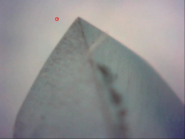
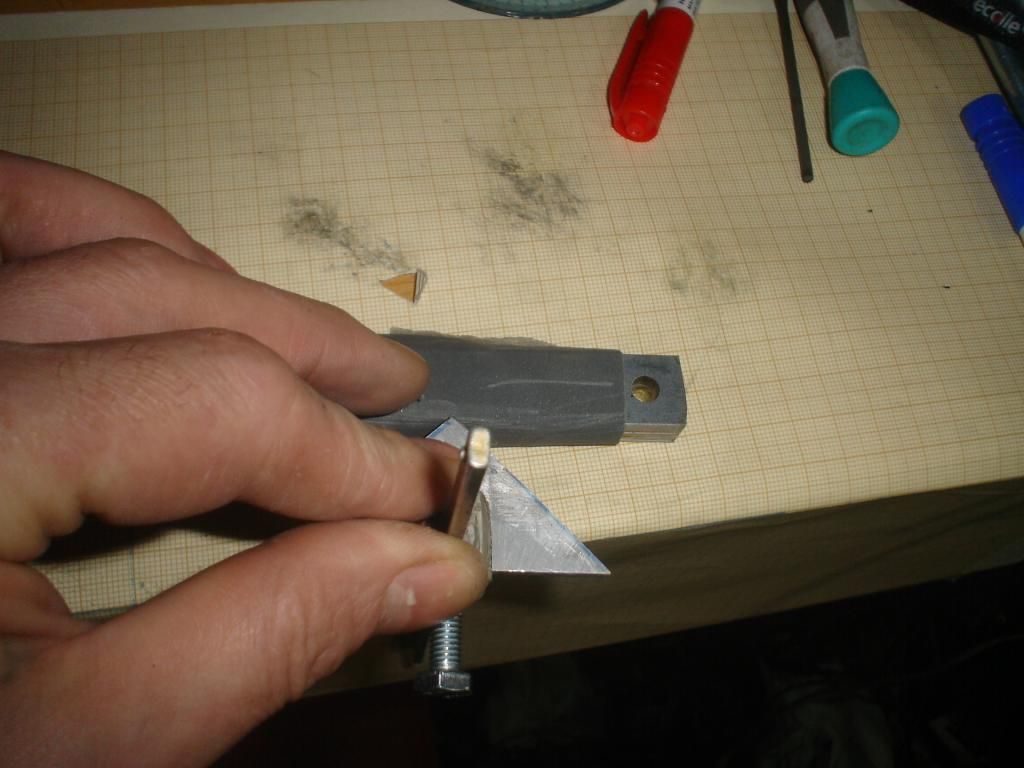
I used silicone for damping,I think tweeters (and way more full ranges!)have too little damping for this application.I damp it like there were no tomorrow. .on the polepice of the speaker,there is a cylinder with a magnet glued at its end,to polarize the feedback coils.I also made a metalic ring for closing the magnetic circuit,but it didn't behave as in computer simulation, it gave clearer and stronger signal without it! (???????)Have a look at the assembly(Only one coil is on):
Image
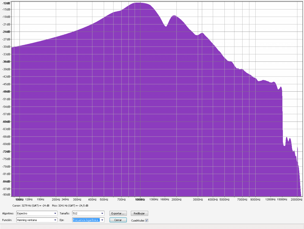
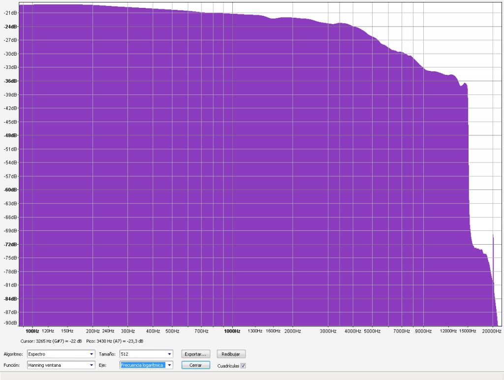
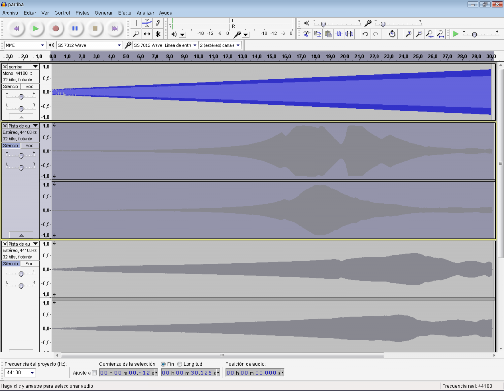
I did'nt build a proper mixing console yet,untill that I'm using a dj mixer(After making shure the feedback phase is inverted respect to the program) and the thrashy PC I'm using has the worst sound card I ever heard,in its mother-f***n-board.it's hermaphrodithe test gave a rollercoaster response. So no spectrum analyse possible.But a sweep up with audacity gives a clue.too many things to do next week!....
Here¡s a video of the test:
I don't know what's to blame for the treble fade out, maybe the pc card, maybe the head capabilities(probably this) or the phase mismatch,(The feedback signal has a delay respect to the program more noticeable in the high pitch). Maybe I have to add fancy things in the feedback loop,(op-amp style)
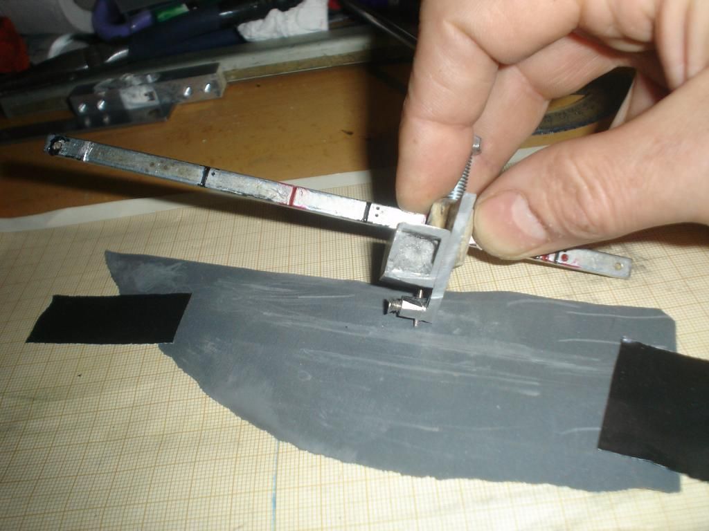
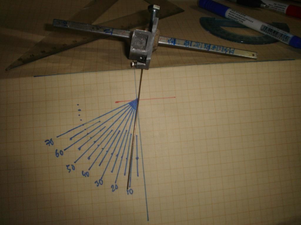
If you are curious abut the rest of the machine...Well here¡s a picture of the whole thing.
Image

Not proud of it.It has some design nonsenses because I change my mind during the process(too long arm, tiny feedscrews...)It was intended for a home made turntable,but I found a cheap direct drive BST PR 436.At the end it barely has torque for embossing under 150 grs.
So, after collecting some data,I'll make everything new!

Cheers!

User avatar
chaosbc
Posts: 144
Joined: Sun May 20, 2012 11:35 am
Location: Paris

Re: DIY Feedback

Post: # 25788Unread post chaosbc
Wed Jun 05, 2013 5:01 am

This is insane. You can be proud of that whatever you said.
I'll probably never go half way of what you achieved. Great job.
------------------------------------------------------
http://www.flickr.com/photos/49941863@N04/sets/72157632396669506/

User avatar
Fela Borbone
Posts: 271
Joined: Thu Mar 07, 2013 5:22 pm
Location: Valencia, Spain

Re: DIY Feedback

Post: # 25789Unread post Fela Borbone
Wed Jun 05, 2013 8:03 am

well, I'm proud of the feedback results,despite I have to work more on it. English is not my home language, maybe it sounds too rude like this...sorry!I mean, the rest of the machine needs complete rebuilding,Noise, tracking issues,rumble, low torque,not brigth treble...But If this is the way to learn,my shame is welcome!

What im not proud in any way is about my film production skills,Not noting that the camera is upside down in the last half of this video:

User avatar
markrob
Posts: 1641
Joined: Wed Nov 28, 2007 1:14 am
Location: Philadelphia Area

Re: DIY Feedback

Post: # 25795Unread post markrob
Wed Jun 05, 2013 10:26 am

Hi,

Very cool! Love your approach to winding the coils and the coil form.

Have you done any testing to see if your feedback is truly reading mechanical motion (actually velocity) or is just receiving coupling from the drive coils? That seems to be the issue with anything I've tried in the past. How much feedback are you able to apply before you start to loose stability? Have you plotted the open loop response of the head (and compared with the closed loop response)? Have you tried monitoring the feedback signal from the head while cutting (while RIAA filter)? If so, does the monitored signal correspond to you what you hear when you playback your cut (this would be a good indicator of the quality of your feedback)?

Mark

User avatar
Fela Borbone
Posts: 271
Joined: Thu Mar 07, 2013 5:22 pm
Location: Valencia, Spain

Re: DIY Feedback

Post: # 25799Unread post Fela Borbone
Wed Jun 05, 2013 2:38 pm

Hello Mark!
I'm not an engineer, so maybe some terms or concepts are bad translated,not exact, or fully wrong,corrections are very wellcome!
As I dismounted the whole spaker, I substituted the drive magnet with metal washers so no motion ocurred, only EMF.All metal parts near the coil affect its electromagnetic performance so thats important for measurement.The feedback magnet, an small round neodymium is situated 10 mm away from drive coil, I simulated with Femm 4.2 (BTW, a free,intuitive interesting magnetic simulator its worth spend a rainy sunday afternoon playing with it) to find out that is far enough for not afecting the coil significantly.At first constructed both coils with a central conecction, so I can chek how much volts are supplyying each,and the fact that they have opposite polarity. The FB coil closer to the drive is more affected and produces stronger signal, so to achieve a real cancel I started peeling off turns out of the bottom coil till it matched.
It can be calculated or simulated,but I found more funny doing it like this.If the distances are respected, you can trust me and save all this work.
Image
You can also double the amount of turns of both equally an use thinner wire,so get more impedance and stronger signal(I will do it one of this days).As the coils are randomly wounded(I mean, not in nice layers) Theres allways some emf pick up, but wery tiny compared with the motion induced.Again, the magnetic circuit in the FB coil is not complete without an outside ring ,maybe with a slot cut lengthwise to aviod shorted turn or Faraday effect.I dont know why it works better without it ,I did something wrong, I´ll check and report if I find it out.
Once the magnets are on and ready to work, feeding a test tone (Sinus 300mA 1 khz) and listening to the FB coil signal (around 100mV) in open loop,the sound changes are obvious when trying to stop the coil motion with the fingers.despite I'm not using simetrical otput(I will when designing the console, now I use a DJ mixer)the hum is not a big issue.
In the video I feed a swep up to the drive,and record the signal coming from the coil,open loop first and closed loop second.When applyin feedback to the mix (closing the loop)I also must rise the "program"fader because the feedback "canibalizes" somehow part of the "prog"signal
Playing a song in the drive, sounds like a telephone in open loop, but get way more body when the loop is closed.
Well my cuts (actually embosses) sound worse than the feedback because I have to lower the mass, find the proper angle,temperatures....Is my first record,I've got no experience! I need lot of practise(and more forum reading :D )...and make some changes in the machine.The video sound is not that bad, but I charged about 7 grams on the needle,and can be seen how the cartridge vibrates at subsonic frequencies.The level is really low compared to a real record, no real treble....Also I burnt some coils recently trying to get more treble... and burned children are scared of fire :lol: !
Image
I dont Know how to measure the amount of feedback... relative to the "program"?(is this a real name for it?) Percentage at the drive?...
well, thanks for your interest!

User avatar
Gus
Posts: 223
Joined: Wed Jun 05, 2013 4:38 pm
Location: Athens,Greece

Re: DIY Feedback

Post: # 25814Unread post Gus
Thu Jun 06, 2013 12:49 pm

Hi!
Congrads for this amazing project!
i have a question for you
what kind of needle do you use?

User avatar
flozki
Posts: 575
Joined: Fri May 19, 2006 4:40 am
Location: switzerland
Contact:

Re: DIY Feedback

Post: # 25823Unread post flozki
Thu Jun 06, 2013 7:31 pm

yes man.
cool. very nice.hehe.i like the papercoils. nice idea.
would be nice to see an openloop plot and then mix in the feedback. in main resonance you should achieve 28-30 dBs at least then you are close to flat.

User avatar
Fela Borbone
Posts: 271
Joined: Thu Mar 07, 2013 5:22 pm
Location: Valencia, Spain

Re: DIY Feedback

Post: # 25825Unread post Fela Borbone
Thu Jun 06, 2013 8:44 pm

Hello Gus,
I use a sharpened cobalt drill point, with the tool shown in the thread "How to emboss" an 1500 sand paper first, and then polished with a 9000 micron sandpaper (sandplastic?) and oil here´s a photo from the tip. The small round circle at the side is 0,018 mm(0,7mils) big, usual diameter of a playback needle's point
Image

User avatar
Fela Borbone
Posts: 271
Joined: Thu Mar 07, 2013 5:22 pm
Location: Valencia, Spain

Re: DIY Feedback

Post: # 25826Unread post Fela Borbone
Thu Jun 06, 2013 9:19 pm

Hello Flo,echte ehre!
Open loop:
Image
Closed loop:
Image
Audacity screen shot:
Image
Rather flat... till around 4khz, then it falls down.Maybe the coil is too lazy for that
The sweep up stops at 15 khz, I didn't spect too much beyond, but a coil BBQ! :D
Cheers!

User avatar
studiorp
Posts: 760
Joined: Thu Nov 01, 2007 6:55 pm

Re: DIY Feedback

Post: # 25830Unread post studiorp
Fri Jun 07, 2013 4:07 am

Sorry for this question, but which type of signal you send to feedback coils ? The same of music program that you must cut ?

User avatar
Fela Borbone
Posts: 271
Joined: Thu Mar 07, 2013 5:22 pm
Location: Valencia, Spain

Re: DIY Feedback

Post: # 25836Unread post Fela Borbone
Fri Jun 07, 2013 10:27 am

SORRY, Everybody.... :oops: Detected that the coils are pickig up more induction than expected, so the curves are not right, I´m positive that the coils get sound,and it will work,but the cancel needs a more fine tunnig...,That explains the "signal canibalism" and the treble drop,The self indution of the drive coil limits its abbility from supplying higher frequencies.
Don´t trust my data yet, I will actualize when possible...Is possible to delete or edit my last post to avoid confusing people?

Is that all?...NO! :oops: in the photo of my stylus, I meassured radius instead of diameter,sorry Gus, here´s the rigth one(I hope):
Image
Sorry again,I've got too much to do and too little time and my fingers go faster than my brain!

User avatar
Fela Borbone
Posts: 271
Joined: Thu Mar 07, 2013 5:22 pm
Location: Valencia, Spain

Re: DIY Feedback

Post: # 25837Unread post Fela Borbone
Fri Jun 07, 2013 10:58 am

Hello Studiorp!
Negative feedback loops are very common in other systems, like sound amplyfiers (But some audiophiles don't like them)The idea is to get a sample of what the system is actually doing and compare whith what is supposed to do, in order to correct the performance.
So, the feedback coils are like little microphones and pick up the motion (sound) of a coil and this signal (inverted!) is mixed with the program and the resulting signal is feed to the amplifier.This acts as a servo, and in theory we get a flat response.
So I don't feed any signal in the coils, they are sources!The problem is that feedback coil pick up also the magnetic field generated by the drive (like a transformer do) and we only want the sound signal! This is why two coils opposite winded cancels the drive electromagnetic force induced,An if they are inmersed in oppositte magnetic fields, the signal generated by movement are added.
This is the teory,but in practise there's lot of "buts".In my first prototype cancellation was achieved, but I changed the design for another reasons and I ruinrd it.
Cheers

User avatar
Fela Borbone
Posts: 271
Joined: Thu Mar 07, 2013 5:22 pm
Location: Valencia, Spain

Re: DIY Feedback

Post: # 25839Unread post Fela Borbone
Fri Jun 07, 2013 1:12 pm

I mean It works, but can be improved, here´s a demo
https://soundcloud.com/felatron/feedback-test
Has been recorded on lexan sheet (policarbonate) with a sharpened cobalt drill point stylus.
No inverse RIAA used as it was recorded direct from another record.
Playback RIAA by audacity
First seconds are cutted without feedback, and lot of clipping is present,despite the average low recording level. After a brief pause, feedback is applied to the mix and the recording increasing level. clippin occurs at higher levels, and the response is flatter. BTW, As I need more treble I choosed the song "Freakshow" by The Treblemakers!

User avatar
studiorp
Posts: 760
Joined: Thu Nov 01, 2007 6:55 pm

Re: DIY Feedback

Post: # 25841Unread post studiorp
Fri Jun 07, 2013 2:26 pm

But the feedback coils are linked togheter ( in parallel ) with the main colis ?

User avatar
opcode66
Posts: 2700
Joined: Sun Nov 08, 2009 10:56 pm
Contact:

Re: DIY Feedback

Post: # 25843Unread post opcode66
Fri Jun 07, 2013 5:10 pm

Signal is only sent to the drive coils. The signal causes the drive coil, paper cone and feedback coil to move. The movement of the feedback coil around a fixed magnet is what creates a very small voltage in the feedback coil. The voltage of the feedback coil is compared to the voltage supplied to the drive coil. The comparison is what allows a special preamplifier circuit to insure the movement generated by the drive coil is what's expected. At points of resonance, the feedback voltage is used to negatively affect the drive voltage. Therefore at points of resonance, the feedback coil voltage generated by the movement of the paper cone can be analyzed and the proper amount of negative correction can be made to the drive voltage such that you account for the physical resonance of the object electronically.
Cutting, Inventing & Innovating
Groove Graphics, VMS Halfnuts, MIDI Automation, Professional Stereo Feedback Cutterheads, and Pesto 1-D Cutterhead Clones
Cutterhead Repair: Recoiling, Cleaning, Cloning of Screws, Dampers & More
http://mantra.audio

User avatar
flozki
Posts: 575
Joined: Fri May 19, 2006 4:40 am
Location: switzerland
Contact:

Re: DIY Feedback

Post: # 25844Unread post flozki
Fri Jun 07, 2013 5:29 pm

nice also your homemade stylii. looks also great. woud be great to see some detaisl how you sharpen them..
a video? hehe.

for the riaa, feedback.
i guess you should get some decent electronics. so get the caruso preamp boards. all you need is on it on a professional level. so you are sure you got good results from the electronic,signal side.
i might will give you some cutterhead-developpers discount because i like this project very much.

also then you can compare your results to other systems. e.g. neumann, caruso and stuff.

User avatar
Fela Borbone
Posts: 271
Joined: Thu Mar 07, 2013 5:22 pm
Location: Valencia, Spain

Re: DIY Feedback

Post: # 25881Unread post Fela Borbone
Mon Jun 10, 2013 11:06 am

Hello Flo,
I've got no talent for video, but maybe this photos help.The proccess of sharpening is simple and it doesn't take long.
First I sand the front "facet":
Image
Sometimes start wiyh rough grain (360)and then 1500.can also be polished with 9000 and oil.The same with nthe sides,Is important use a flat surface and keep the tool firm on it:
Image
The edges souppossed to be straigth are little rounded, but that is not a big problem if taked into account when measuring the angle.Sliding the bar the resulting heel angle varies Here is how I calibrated the tool (and confirmed with the microscope):
Image
I get fair results when embossing whit a heel of around 30deg to the disc surface. I use thermocoll to isolate and glue the nichrome wire around.

It will be great to have a Caruso as preamp! thanks for the offer!, I send PM to you.
Cheers

User avatar
Jonaa
Posts: 3
Joined: Thu Jun 27, 2013 8:58 am
Location: Stockholm, Sweden

Re: DIY Feedback

Post: # 26199Unread post Jonaa
Fri Jun 28, 2013 6:26 am

Fela Borbone wrote:Hello Studiorp!
Negative feedback loops are very common in other systems, like sound amplyfiers (But some audiophiles don't like them)The idea is to get a sample of what the system is actually doing and compare whith what is supposed to do, in order to correct the performance.
So, the feedback coils are like little microphones and pick up the motion (sound) of a coil and this signal (inverted!) is mixed with the program and the resulting signal is feed to the amplifier.This acts as a servo, and in theory we get a flat response.
So I don't feed any signal in the coils, they are sources!The problem is that feedback coil pick up also the magnetic field generated by the drive (like a transformer do) and we only want the sound signal! This is why two coils opposite winded cancels the drive electromagnetic force induced,An if they are inmersed in oppositte magnetic fields, the signal generated by movement are added.
This is the teory,but in practise there's lot of "buts".In my first prototype cancellation was achieved, but I changed the design for another reasons and I ruinrd it.
Cheers
Finally I found a good explanation of this principle! This helped me alot!

Haha, This is my first post so it might sound extremely unprofessional and stupid, but I have a question. Is it possible to make a feedback system based on a moving magnet, surrounded by a stationary coil, instead of a stationary magnet, surrounded by a moving coil, like in a ordinary system? I guess it's not the most optimal construction, but is it worth a try? would the weight of the magnet(s) be a problem?
Musician and music producer
from Stockholm, Sweden

https://www.facebook.com/RedButtonSyndrome
https://soundcloud.com/am-baterror

User avatar
Fela Borbone
Posts: 271
Joined: Thu Mar 07, 2013 5:22 pm
Location: Valencia, Spain

Re: DIY Feedback

Post: # 26201Unread post Fela Borbone
Fri Jun 28, 2013 10:19 am

Hello Jonaa,
Yes, moving magnet can also work,But the weight is the reason of my choice.Making shure each coil is immersed in opposite magnetic fields
My feedback system work well and cancels signals up to around 2-3 khz.Confirmed, the mixer was guilty of my last doubts,The cue knob didn't isolate properly both sources.So its able to correct the main resonance, but not the whole spectrum.The graphics are more or less rigth.It needs a bandpass filter for the feedback,to be (half)usefull.The system was larsening at 50 khz,I didn't notice..my cheap AC amperimeter didn't measure that high frequency,I didn´t hear nothing, just smelling the coil burning...
The delay between all signals (both audio and magnetic coupling)becomes very noticeable at 5 mhz creating a phase shift that ruin all calculations made at 1khz.Audio start substracting instead of adding.
Im working now in a more compact design.Also using 110 and -60 turns of 0.05mm wire for feedback and around 40 turns of 0.16mm wire for drive. The coil assemble is becoming heavy... near 1 gram.
BTW, in the hand drawing above in older post,both AWG are permuted.
Hope to get better results soon.

Years ago I thinked that Faraday rings or shortening rings were just a comercial excuse to charge some extra euros on a speaker.But after reading this papers:
( http://www.diy-audio.narod.ru/litr/FaradayRingsVoiceCoilImpedance.pdf ) I made some experiments and get convinced of its benefits.But a cutterhead works in an exterme scenario and the ring occupies valuable gap space (about 1/3 of the coil thickness to be efficient) and also generates some heat.But, as I dont want to act over the drive impedance,but the coupling, placing such a ring between it and the FB coils, "eats" lots of induction,Still experimenting with it, but show promising results.
Cheers!

Babooino
Posts: 101
Joined: Thu Aug 29, 2013 6:24 pm

Re: DIY Feedback

Post: # 27180Unread post Babooino
Fri Sep 20, 2013 7:55 pm

Fela Borbone wrote:well, I'm proud of the feedback results,despite I have to work more on it. English is not my home language, maybe it sounds too rude like this...sorry!I mean, the rest of the machine needs complete rebuilding,Noise, tracking issues,rumble, low torque,not brigth treble...But If this is the way to learn,my shame is welcome!

What im not proud in any way is about my film production skills,Not noting that the camera is upside down in the last half of this video:
Haha great music!

Post Reply