Neodymium and other mods in a Presto 1-C

This is where record cutters raise questions about cutting, and trade wisdom and experiment results. We love Scully, Neumann, Presto, & Rek-O-Kut lathes and Wilcox-Gay Recordios (among others). We are excited by the various modern pro and semi-pro systems, too, in production and development. We use strange, extinct disc-based dictation machines. And other stuff, too.

Moderators: piaptk, tragwag, Steve E., Aussie0zborn

Post Reply
User avatar
Fela Borbone
Posts: 270
Joined: Thu Mar 07, 2013 5:22 pm
Location: Valencia, Spain

Neodymium and other mods in a Presto 1-C

Post: # 31401Unread post Fela Borbone
Sun Sep 14, 2014 8:33 pm

Hello!
Here I will explain some mods in a Presto 1-C,they concern 3 parts of the head: Magnet, coils and damping.
I think it can apply to the 1-D as well, as they are not too different.I'm not an engineer, so If an educated reader or anybody, notes that something is wrong or can be said better or whatever,corrections are wery wellcome
This mods are reversible, so I keep the parts and can convert it back to its primitive configuration if feeling nostalgic.

1-MAGNET
As far as I know this magnet is of the alnico type, I don't know if in my unit is weak or not,It seems to have power but I was expecting more output.
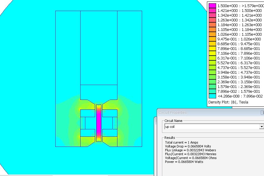
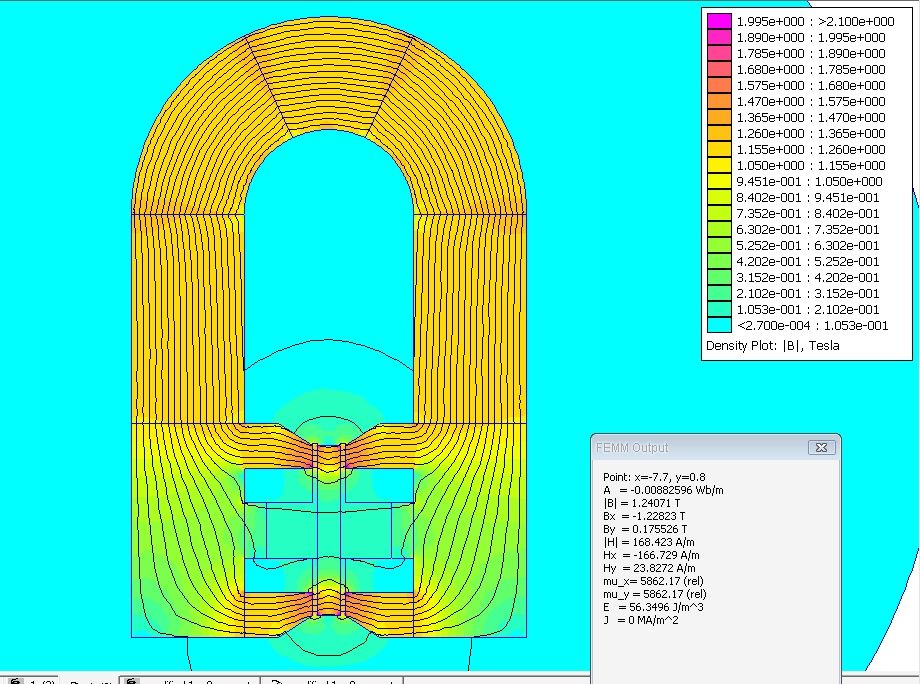
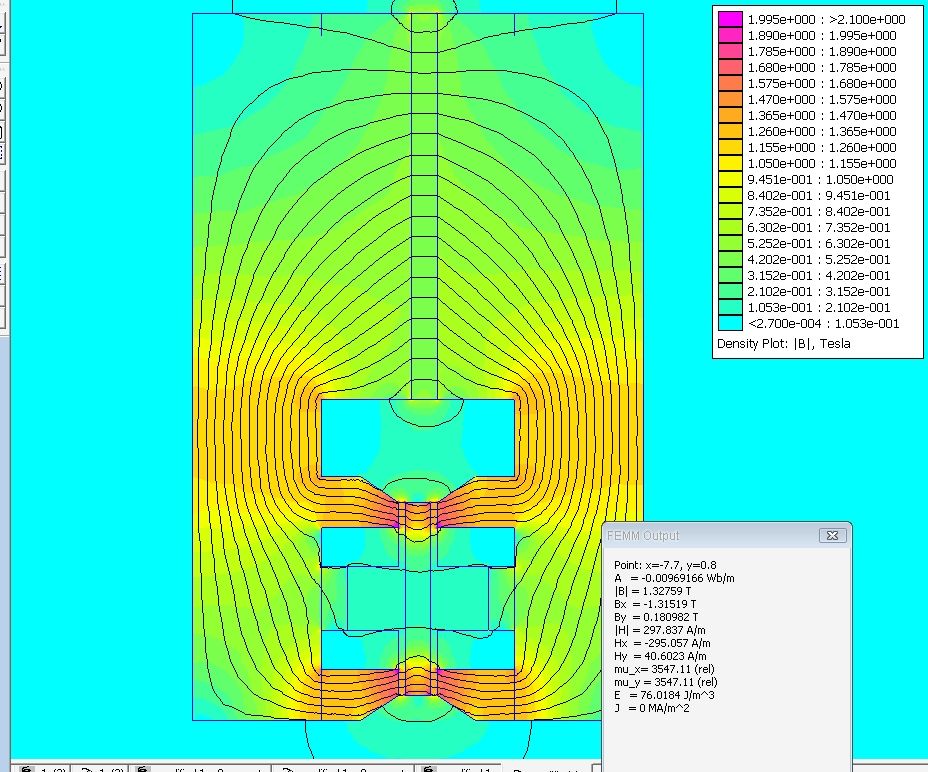
In this magnetic simulation shows Alnico 5,the most powerfull of alnicos avalaible in my simulator.Alnico8 yields 0.7 Tesla in the armature, Alnico6 1Tesla and Alnico5, 1.25Tesla.
Armature and polepieces have similar potential.

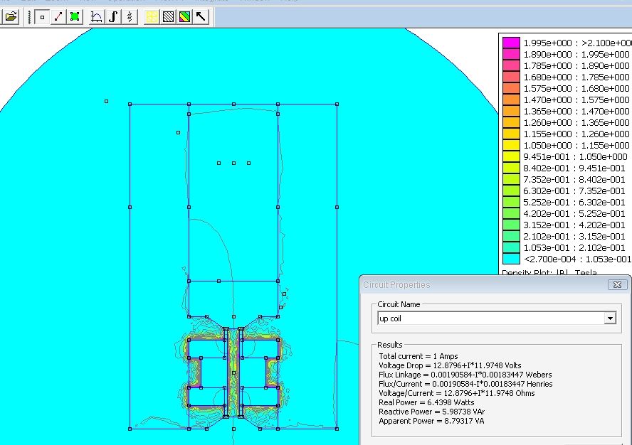
The output window display data concerning the armature.is simulated as iron, as I dont know which material is it.anybody knows?:
Image


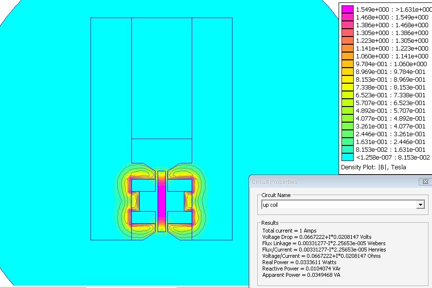
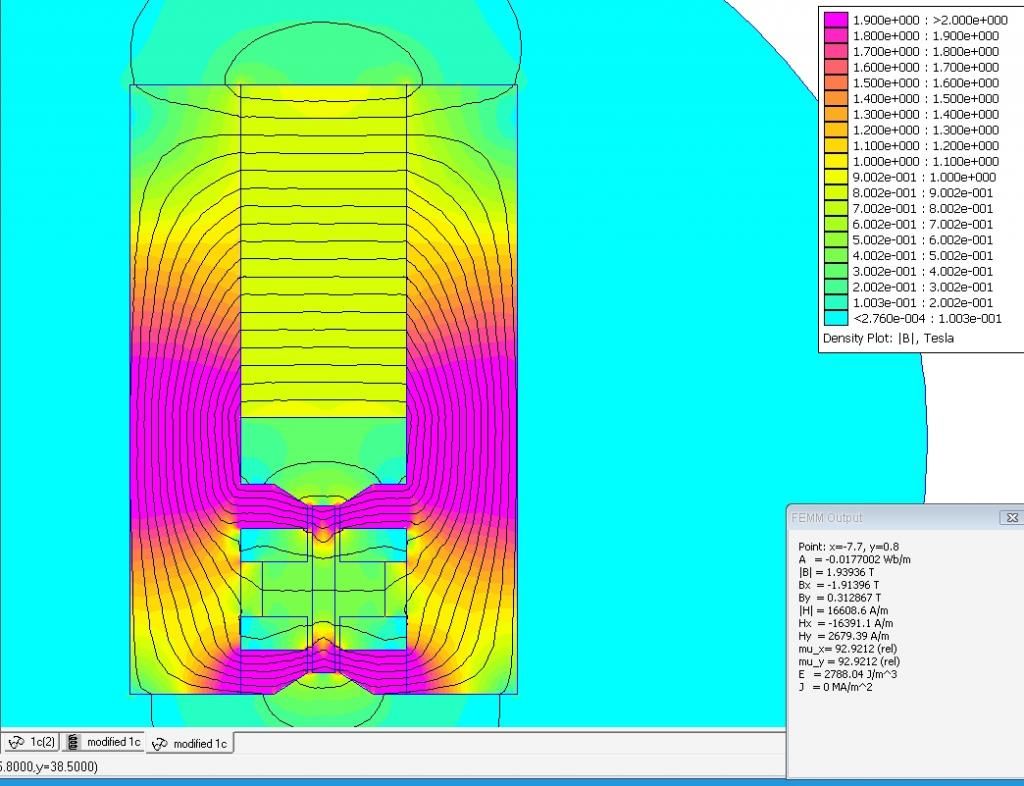
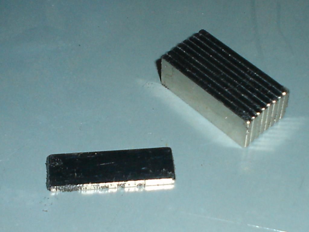
one cheap 2mmx10mmx30mm,neodymium brings barely more flux density than the whole horseshoe alnico, yields 1,32 Tesla in the armature:

Image

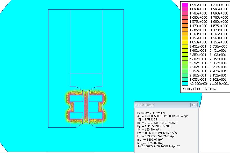
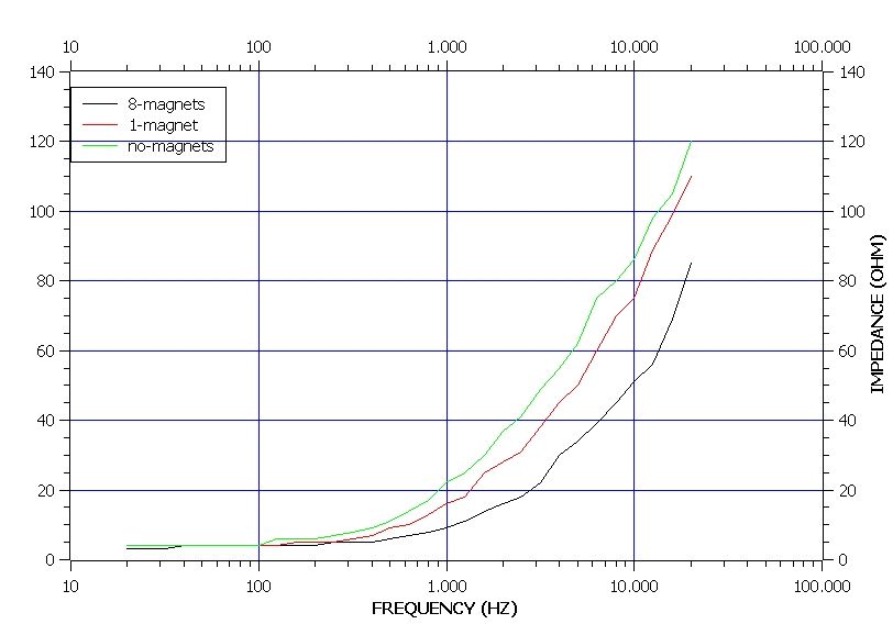
Care must be taken with the neodymium as they tend to magnetize every iron tool or instrument around, especially if it jumps and knocks his victims.Here, 8 of this magnets nearly reach 2 Tesla,
Image
the head without shell, looks like this:
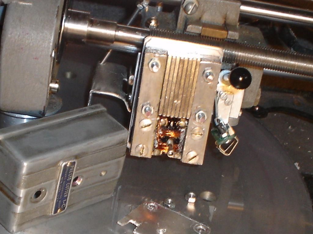
Image
The magnets:
Image
The magnets are linked to the polepieces with two parts made with laminated iron, comig from a scrap transformer.They are screwed in the polepieces in the same way the magnet was.Back side in the pic is front in the head:
Image

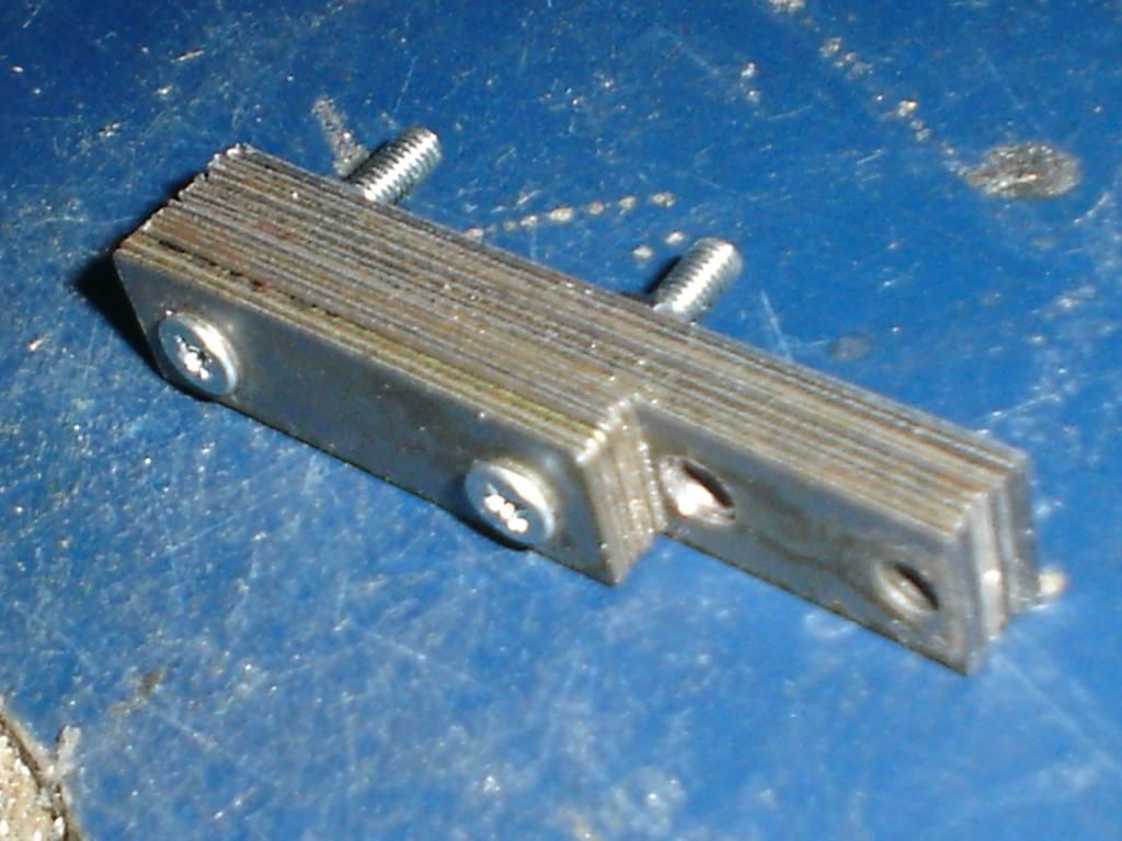
I had to remove a connections thing to house the magnets.Instead of laminated Iron, a solid iron bar will act the same, as static magnetic fields dont generate eddy currents and the coils magnetic circuit is conducted thru the polepieces.


One point I was worried about is where are the limits of the magnetic flux feed in the polepieces,to aviod saturation in the armature, as it will affect the way is driven by the coils.
but, for my surprise,I noticed no big distortion with the new magnet.I wonder whats happening, how a linear changing magnetic field interacts with an metal magnetically saturated,in which the behaviour will be not linear.But the resutant force seems proportional to the drive...
I had no instruments to measure distortion, but audio is nice, for a 70 years old head, and sinewaves good looking.
Maybe because this operations are vectorial,direction dependant, or because the simetrical arrangment of the coils.Any clue why I dont get saturation distortion?
I am positive that the armature is saturated, nearly 2 Teslas, acording with simulation.
Anyway, if is not broken, dont repair it.All what I experience with this change is a monster sensitivity.It allowed me to adjust the gap a little wider and use shorter stylus.
More to come soon,

User avatar
powerstrip
Posts: 269
Joined: Sun May 08, 2011 10:02 am

Re: Neodymium and other mods in a 1-C

Post: # 31448Unread post powerstrip
Thu Sep 18, 2014 9:25 am

hey nice work with these heads as of late. The re-magnetizing thing is big help for lots of people

i read through the post but saw no description of the program you used to scan those magnetic frequencies. Is it just a simulator or are you scanning the head with a device?

User avatar
EpicenterBryan
Posts: 738
Joined: Sun Aug 10, 2014 9:01 pm
Location: Eugene, OR USA

Re: Neodymium and other mods in a 1-C

Post: # 31460Unread post EpicenterBryan
Fri Sep 19, 2014 12:05 am

powerstrip wrote:i read through the post but saw no description of the program you used to scan those magnetic frequencies. Is it just a simulator or are you scanning the head with a device?
I think Fela is using a modeling program to simulate the magnet field flux density as shown in the photos.

I'm also thinking he may be running an amp designed for 8 ohm output on this super high field head since I don't think he changed the coil configuration from 15 or 500 ohm to 8 ohm. So, having a stock head with stock coils being run with a mismatched output impedance amp (a consumer 8 ohm amp) this stock head with increased magnet field density (efficiency) , may actually work fine with what he has created.

We all know we can't run a normal 500 ohm head with an 8 ohm amp right? But if the head is this much more efficient, who cares if any power is lost due to load imbalance. He may have found the holey grail of making a head compatible with an 8 ohm amp! Just kick up the internal magnetic fields!

So, I will pose the question to Fella... What impedance was your head before you started? Stock values would be 15 ohm, or 500 ohm. Did you rewire the head for some other value (like 8 ohm) , and if not, what is it wired for now? Also, what output impedance is the amp you are currently using with you modified head?

Bryan

User avatar
markrob
Posts: 1634
Joined: Wed Nov 28, 2007 1:14 am
Location: Philadelphia Area

Re: Neodymium and other mods in a Presto 1-C

Post: # 31464Unread post markrob
Fri Sep 19, 2014 8:01 am

Hi,

I've been following this thread with interest. What makes you so sure your simulation is correct? My experience with SPICE and other simulators has been quite rocky over the years. I normally don't trust them at first glance as they are only as good as the models used and the care with which the simulation is setup. You would expect the head to follow the equation F=BLI where B is the magnetic field, L is the length of wire in the field, and I is the current in the coil(s). In your simulation, you are finding that the armature is sitting at a 2T level of magnetization. Is this really true? Maybe this is correct. If so, there is no room to increase the armature magnetization. However, you could buck the field if the current in the coil opposite in polarity. Can you simulator show the effect of the field around armature when a DC current is passed through the two drive coils? Note that the two coils are wound push-pull. That might shed some light on the problem.

Mark

User avatar
Fela Borbone
Posts: 270
Joined: Thu Mar 07, 2013 5:22 pm
Location: Valencia, Spain

Re: Neodymium and other mods in a 1-C

Post: # 31468Unread post Fela Borbone
Fri Sep 19, 2014 2:38 pm

powerstrip wrote:hey nice work with these heads as of late. The re-magnetizing thing is big help for lots of people

i read through the post but saw no description of the program you used to scan those magnetic frequencies. Is it just a simulator or are you scanning the head with a device?
Hello! I'm changing the magnets, not re magnetizing (maybe it means the same in english) Here is an interesant thread about charging the magnets, maybe a simpler solution if the magnet is weak http://www.lathetrolls.com/viewtopic.php?f=1&t=5207

Yes, I'm using a simulator called FEMM. The good side, it's free ( http://www.femm.info/wiki/HomePage ) but no 3d modelling (only planar and axisimmetric).
Other good choice is the student version of quickfield, but modelling is limited to very simple models.This are the only options for my poor old pockets.
Agree with Mark about computer simulators.I can trust them for digital things.For analog electronics and magnetics can give a good clue but the bench have allways the final word.
Mi post ended with a question more than a statement.I think the BH curves in this simulator are very generous.This curves can be edited, but a search of "iron bh curve" can lead to different results.
I think laminated iron saturate well bellow 2 Tesla(1.5 T?).Yes the simulation is as good as the data introduced, and what the simulator suposes what it should be.
As a practical test I tried the head whith 1 to 8 magnets, of course closing the magnetic circuit whit iron blocks.The recorded level increased till IIRC 5 magnets, then not noticable change if adding more,what indicate that over that number we are just wasting magnets(magnetically saturated).It just looks nicer with all the space filled of cheap magnets.
I lost my written notes on this subject, but I thing it was like this.

My 1-C was originally 500.ohm, bad match for a solid state, so I had to rewind it to lower impedance.I also lost my notes on this, but I think it was 200 turns(maybe a few less for space limits?) of 30 AWG,each coil that yields 3,5 ohms DC.DC resistance dominates over reactance in the middle bass so I wounded feedback coils to correct this problem.They were hair-thick and maybe over 50 turns each.But it can be solved with EQ,anyway.I'll write more about the coils in the future, when I find my lost papers.

Simulation of the coils operating at 1A DC(magnet is disabled):
Image
here IIRC 20hz:
Image
1k:
Image

As a computer simulation, data should be not trusted 100% but gives the clue that induced magnetic flux concentrates in different areas than the one supplied by the magnet.This may answer some of my questions.I wish I had the "magnetic camera" described by Opcode 66 some time ago.This can just scan the magnetic fields and give accurate results.
Is a benefit replace the magnet?
For me was, but I can't tell if my alnico was weak,despite it seemed to have respectable force.But I didn't measure It.It seems that, despite the saturation, even only one Neodymium supplies more magnetic flux.How much? the answer is "more".
Here, I described what I did, and, the best I can, my results. I hope somebody can find it usefull, but act at he's/she's own risk.
If somebody follows the same way I'll be glad to read reports. Thanks.

User avatar
Fela Borbone
Posts: 270
Joined: Thu Mar 07, 2013 5:22 pm
Location: Valencia, Spain

Re: Neodymium and other mods in a Presto 1-C

Post: # 31472Unread post Fela Borbone
Fri Sep 19, 2014 5:11 pm

ooops! wrong pics, properties of coil circuits are wrong in the last pics, here are the rigth ones. It applies to one coil only,so 1,35 0hms DC is displayed but both coils gives 3,70 (similar to what is directly nmeasured)
DC:
Image
1Khz:
Image
Sorry, and thanks for reading!

User avatar
Presto Repairs
Posts: 81
Joined: Tue Oct 28, 2014 8:02 pm
Location: Melbourne - Australia

Re: Neodymium and other mods in a Presto 1-C

Post: # 32074Unread post Presto Repairs
Thu Oct 30, 2014 8:40 pm

I have 2 questions.

1st - Looking at the photos of the head - how is the cover secured to the head as the magnets above the coils appear to block the cover screw hole?

2nd - With so many strong magnets - how did it effect the impedance measurement of the coils compared to the original magnet?
Presto Repairs - Repair/Restoration service for Presto Recording Corp cutterheads and other similar styled brands such as Audax, RCA & Universal

User avatar
Fela Borbone
Posts: 270
Joined: Thu Mar 07, 2013 5:22 pm
Location: Valencia, Spain

Re: Neodymium and other mods in a Presto 1-C

Post: # 32159Unread post Fela Borbone
Wed Nov 05, 2014 12:47 pm

Hello again,
I'm having severe personal problems of various kinds, so I'm not posting as often as I wish,sorry.
Hello Presto Repairs! good to have repair service for this heads, good luck!
About first question, .In the original head, the damping rubber has a metal bar at the top that holds the cover by means of a screw and itself to the body with two screws on the sides.If using the original damping,rubber can be fixed on top of the magnets,if a part used for connect the coil wires to the external cables is removed and heatshrink tube is used instead. But I dont use the original rubber.I found the part used to hold the armature in the rubbber is heavy.The original 3.73 grams are reduced to 3.03 (metal stylus included).This two plates with 4 screws can be "screwed out"the armature. May seem not too much at first sigth, but as as it moves describing an arch, wheigt gains importance as it is placed away from the axis.I cutted my own damping from a rubber sheet an a tiny hole for the armature(It fits very tight).Its enough for the purpose.In the top photo there is a partially visible alluminium plate that has the function of holding the cover, M3 nuts at the side and a self tapping screw in the middle.

About second question,Yes, anything altering the magnetic conditions around the device affects the impedance:
Image
The movement of the armature don't produce the crazy spikes usual in moving coils, I did some test with aluminium in the gap(blocking the movement) and I didn't notice any big change
Consequence of this is that the turnover frequency at wich the bass fades out at 6 db octave also changes.If using feedback it corrects by itself.If not,a bass bost will work also well,as is usually needed if using a modern amplifier.As most of you will already know, this point is present in all moving iron cutterheads (ok, maybe some exceptions?)and was used as a frequency caracteristic, giving constant amplitude to bass at a time when there was not a RIAA standard for that.So "it's a feature, not a bug"
Thanks for reading

User avatar
Fela Borbone
Posts: 270
Joined: Thu Mar 07, 2013 5:22 pm
Location: Valencia, Spain

Re: Neodymium and other mods in a Presto 1-C

Post: # 32161Unread post Fela Borbone
Wed Nov 05, 2014 12:53 pm

I have to point that I made the impedance masurements with non hi accuracy system,just comparing the head at variuos frequencies (1/3 octave) with a pure resistance.So is just a rough view,not a high resolution thing, but enough for me.

Post Reply