Wagner Nichols blanks & repair?

This is where record cutters raise questions about cutting, and trade wisdom and experiment results. We love Scully, Neumann, Presto, & Rek-O-Kut lathes and Wilcox-Gay Recordios (among others). We are excited by the various modern pro and semi-pro systems, too, in production and development. We use strange, extinct disc-based dictation machines. And other stuff, too.

Moderators: piaptk, tragwag, Steve E., Aussie0zborn

Post Reply
User avatar
deweydb
Posts: 6
Joined: Fri Sep 10, 2010 7:11 pm

Wagner Nichols blanks & repair?

Post: # 10511Unread post deweydb
Fri Sep 10, 2010 7:17 pm

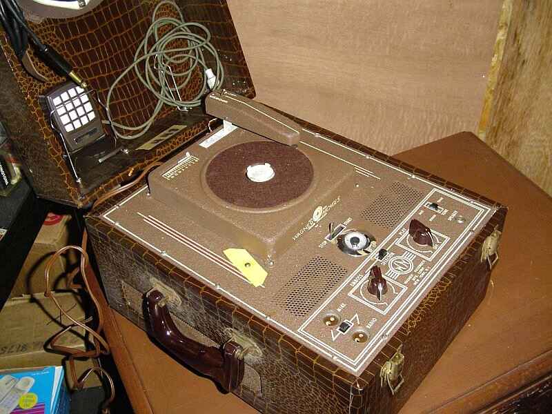
I am considering purchasing a wagner nichols embosser which is for sale locally in my city.

Two things though, first, how difficult would it be to find / make blanks for this machine?

second, the machine is being sold in "as-is" condition. Do you think it would be very difficult to repair/find replacement tubes for this type of machine?

Thanks SOOOO much in advance for any advice you could share with me!

Cheers,
Dewey
Image

User avatar
agfamatic
Posts: 17
Joined: Sat Jul 31, 2010 10:27 am
Location: gnesta, sweden

Post: # 10526Unread post agfamatic
Sat Sep 11, 2010 2:58 pm

that looks like nice cutter. aboute tubes/valves there are some web sides that sell lots of NOS tubes but the price can vary depending on what type of tube you need i think you will find a lot of good tube companys if you just google search "NOS vacuum tubes" and of corse its importent that you order the right kind of replasement tube otherwise you might blow somthing up.

but from what i have heard (and my farly limited experience in valve electronics) the valves is often not the problem its more often failing capasitors so you will propobly not need to chage eny tubes but you will propoby change some bad caps and caps are not that expencive but you need to find some that have the corect value.

the only company i know of that still makes blanks for cutting is Apollo but they seens to farly expencive so you might have to use old blanks or make your own blanks out of picknic plates or cutt on CDs.

User avatar
markrob
Posts: 1636
Joined: Wed Nov 28, 2007 1:14 am
Location: Philadelphia Area

Post: # 10528Unread post markrob
Sat Sep 11, 2010 4:55 pm

Hi,

Restoration of the electronics should be pretty easy. As was stated, caps are usually the problem. Tubes, both NOS and used are normally easy to find. You may be able to find service info as this may have been covered by Sam's Photofact or Riders. Mechanically, you will probably need to flush out old dried grease and may need to replace or re-condition any rubber idlers or belts. The big issue would be the embossing head. If this is a magnetic device like found in Soundscribers, you should be ok. If its a crystal based unit, it is likely dead and will need to be re-built. This may not be easy. West-tech is a good source for this as well as complete re-building and restoration.

http://www.west-techservices.com/index.htm

You should be able to use PVC, Mylar, or Acetate film found in art supply stores as blank material. I suspect you could also use plastic picnic plates as blanks. If you search here, you should find info on that.

Hope this gets you started.

Mark

User avatar
deweydb
Posts: 6
Joined: Fri Sep 10, 2010 7:11 pm

Post: # 10548Unread post deweydb
Tue Sep 14, 2010 1:47 pm

Hello,

Thanks for all the wonderful info, you guys totally made my day!
I do feel quite comfortable replacing old caps, tubes & transformers. But the mechanical stuff (belts, etc) might be a bit more of a challenge for me. I am also very curious as to how i could check if it is a magnetic or crystal based unit? I tried googling for Sam's Photofact and Riders, but didn't find much, do you have some links to these pages?

p.s. thanks for the tips on homemade discs, this part is super cool!

User avatar
agfamatic
Posts: 17
Joined: Sat Jul 31, 2010 10:27 am
Location: gnesta, sweden

Post: # 10550Unread post agfamatic
Tue Sep 14, 2010 3:37 pm

deweydb wrote:Hello,

Thanks for all the wonderful info, you guys totally made my day!
I do feel quite comfortable replacing old caps, tubes & transformers. But the mechanical stuff (belts, etc) might be a bit more of a challenge for me. I am also very curious as to how i could check if it is a magnetic or crystal based unit? I tried googling for Sam's Photofact and Riders, but didn't find much, do you have some links to these pages?

p.s. thanks for the tips on homemade discs, this part is super cool!
if you not feel comfortabe working on the electronic parts you probobly should send it to a reparir shop that have experiense working on old valve/tube based stuff. i personaly dont have eny experiense sending in eny stuff to a repair shop for repairs (for economic resons i usuly fix all my stuff myself even if it sometimes is a pain in the ass) so i realy cant recomend eny good repair shop but i know that many people here likes West-tech.

on old unit like that you never realy knows in what state the mecanical stuff is you might get lucky and you only need to change some rubber belts or lady fortune vomits on you from a great hight and you have a mecanism full of rock hard or even melted ruber rollers that needs to be complitly rebuild. but of corse thats also some of the thrill buying old ancient equipment you often dont know what you will get.

but one thing you could do before you will make up your mind if you are going to buy it is to ask if the seller could demonstate if its working.

User avatar
deweydb
Posts: 6
Joined: Fri Sep 10, 2010 7:11 pm

Well i bought it...

Post: # 10551Unread post deweydb
Tue Sep 14, 2010 4:34 pm

I just couldn't pass up the opportunity to own a machine like this! So i bought it. It came with a stack of blanks which is nice.

I will post back here with some progress and more photos as work goes on.

User avatar
markrob
Posts: 1636
Joined: Wed Nov 28, 2007 1:14 am
Location: Philadelphia Area

Post: # 10552Unread post markrob
Tue Sep 14, 2010 5:45 pm

deweydb wrote:Hello,

Thanks for all the wonderful info, you guys totally made my day!
I do feel quite comfortable replacing old caps, tubes & transformers. But the mechanical stuff (belts, etc) might be a bit more of a challenge for me. I am also very curious as to how i could check if it is a magnetic or crystal based unit? I tried googling for Sam's Photofact and Riders, but didn't find much, do you have some links to these pages?

p.s. thanks for the tips on homemade discs, this part is super cool!
Sam's is availalbe here:

https://www.samswebsite.com/photofacts.html

I did a quick check and did not find the mfg listed, but it might show with a chassis or model number search. Sam's only goes back to the early 50's, so it might not cover this unit.

This web site may be able to help.

http://www.radioera.com/riders.asp

I have the complete Rider's on CD. So if you have the full model number I'll try to look it up for you.

Keep in mind that you can probably get by without any schematic as these are usually pretty simple devices. Basically just like a phonograph.

I would avoid plugging the unit in without doing some cap replacement. The electrolytic's are usually dried out and could be shorted. I start with all tubes removed and check the power transformer for proper filament voltages and the HV supply (hopefully its not a series string transformerless design). Then, add the rectifier see if the DC B+ comes up to a reasonalbe value. Usually, the only other critical cap(s) are the those that couple the phase inverter or driver (if single ended) to the power output tube(s). If these are leaky, the tubes will be biased into conduction and could be damaged along with the output transformer.

You can probably tell if the embossing head is magnetic by measuring it with a ohmmeter. I would measure with the head out of the circuit. If you get a resistance reading anywhere from 4-1000 ohms, I'd assume its magnetic.

Should be a fun restoration project.

Mark

User avatar
deweydb
Posts: 6
Joined: Fri Sep 10, 2010 7:11 pm

Progress....

Post: # 10579Unread post deweydb
Thu Sep 16, 2010 10:56 pm

So I pulled it apart today and found a number of interesting things. There were 3 solder connections that had become completely disconnected. I noticed that someone had done work on this machine in the past. They replaced one of the old (electrolytic?) caps with 2 newer looking caps. (I think they used two because the old cap is 20, 20, 20, 20 and the two new ones are 40, 40, 20, 20 and a 20, 20. The way it is wired up it looks like they were using just the 20, 20 from the one cap, and the 20, 20 of the other to make it a match to what used to be there).

I probed the caps for shorts, and found none, but beyond this i'm not sure how to test them.

I pulled all the tubes out and powered it up, then metered the secondary of the input transformer. I got a reading of 689Volts. One of the tubes, a 6E5 seems quite blown to me, but without a tube tester i cannot be sure. Going to bring all the tubes in to the electronics store tomorrow and test them.

I pulled the head off and sure enough it is a crystal head. It is a Sure Crystal Pickup Cartridge and has W428 printed on one side, and 1152 printed on the other. Does this mean anything to anyone?

Here are some pictures:
Image
Image
Image

User avatar
markrob
Posts: 1636
Joined: Wed Nov 28, 2007 1:14 am
Location: Philadelphia Area

Post: # 10582Unread post markrob
Fri Sep 17, 2010 10:24 am

Hi,

Interesting. I guess they used the Shure as an embossing head and playback pickup. Clever. Probably will need to be rebuilt at West-Tech.
Given its a crystal, that would imply its driven directly off of the plate(s) of the output amplifier. What is the tube complement of this machine?

The 6E5 can be costly to replace. These are quite often dim due to age. Depending on how much you want to keep it original, you could elect to not replace it and use a meter as the level indicator.

Its also a good idea to replace all of the old paper caps as these are usuallly leaky. Does not look like there are too many to do. The FP style electrolytic should be replaced. You can buy new, but these tend to be expensive. I'd opt to replace with under chassis single section modern axial lead caps. They are readily available.

Since the whole restoration revolves around the head, I'd first get in touch with Gib at West-Tech and see if he thinks his re-build will work in this application. Based on some current posts, that may be a bit difficult as he does not seem to be responding to emails or phone calls in a timely manner right now. You might want to test the pickup/cutter first. If you have acess to a scope, connect the pickup to the input and tap the stylus, you should see a volt or two peak output on the screen. You could also hook the pickup to the input of an audio amp and see if it reproduces a click when you tap the stylus. Since these are high impedance devices, try to find an amplifier with an high impedance line level input (a guitar amp would be a good choice).

Mark

User avatar
agfamatic
Posts: 17
Joined: Sat Jul 31, 2010 10:27 am
Location: gnesta, sweden

Post: # 10587Unread post agfamatic
Fri Sep 17, 2010 6:10 pm

becoase ther have been someone mesing arond with the electronics before you it might be a good idea to check all the wireing so that nothing is lose or shorted.

btw on the picture of the electrolytics it looks like ther are one wire that have come lose. :shock:

User avatar
deweydb
Posts: 6
Joined: Fri Sep 10, 2010 7:11 pm

some progress

Post: # 11485Unread post deweydb
Sat Nov 20, 2010 7:58 pm

So I've managed to replace all the old caps, and i replaced some of the broken tubes. I also sent the stylus to Gib, and got it back fully restored! (thanks gib!!)

Here is a pic of the insides with the new caps. It looks slightly different than this now as i have replaced one of the resistors as well because the lead broke off during my work.
Image

The machine now runs well, the platter turns consistantly without noticable distortion to the speed.

The tonearm tracks the records well, and i can even run it in embos mode and it will slightly embose the blanks.

The only remaining problem is that the ebosed discs don't get a very strong signal written to them, they all sound somewhat quiet, with a lot of noise (crackle) in the background. Like a really bad signal to noise ratio.

I noticed that at the back of the machine, attached across the input/output wires to stylus, is 4 series neon lamp bulbs. At least i think they are neon lamp bulbs, i am attaching a picture of them.
Image
one of them 4 bulbs is no longer even connected and one looks burned out, and this looks like it has been repaired twice in the past, as there are two different layers of tape wrapped around them and one tape looks more dated that the other tape.

I went to the electronics store and asked someone about them, they suggested that i buy some neon lamp bulbs and try wiring them up. the only neon bulbs they had are 90Volts AC, and require a 100k resistor (in series?).


If i was to wire up four of these in the same place it would imply that the output of this wright head can output as much as 360 Volts AC?!?

This seems really strange to me because usually stylus cartridges output voltages in the range of 100-500 mV.

What am i overlooking here? What is the purpose of these bulbs? Should it try to insert the new ones as a replacement?

Image

User avatar
deweydb
Posts: 6
Joined: Fri Sep 10, 2010 7:11 pm

Further update

Post: # 11488Unread post deweydb
Sat Nov 20, 2010 9:29 pm

We replaced the four old neon bulbs with the four new ones after metering the output of the emboser when in embose mode and a very hot voice signal running into the machine through the microphone. This produced voltages on the scale of what would be expected to power these four neon bulbs, so we decided to solder in the replacements.

They work great, but i still don't really understand the purpose of the bulbs other than some mearly cosmetic result of making the machine glow from the inside when it is embosing a very loud sound.

We managed to get the emboser to write a (fairly distorted) cut to a record, and there is still quite a lot of background noise.

Does anyone have any ideas on how i could reduce the noise in the circuit? or make the write head cut a cleaner signal?

Thanks,
Dewey

User avatar
markrob
Posts: 1636
Joined: Wed Nov 28, 2007 1:14 am
Location: Philadelphia Area

Post: # 11501Unread post markrob
Sun Nov 21, 2010 4:15 pm

Hi Dewey,

Looks like you are making great progress. If I had to guess, I'd say the neon's are in the circuit to act as a poor man's limiter. They function much like a modern zener diode and were often used in voltage regulator circuits. Do you believe that these were original to the unit or added later? Were they visible or were they encapsulated? If they were visible, they could also have been used as a peak overload recording indicator rather than a limiter (or perhaps both).

As far as background noise goes, that may be more a function of the material you are using and/or the conditon of the stylus. Is the same background noise present if you disconnect the wires to the head and emboss a silent groove?

Mark

Post Reply