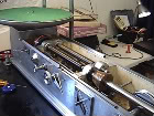
Since my tape deck only has four outputs (2 preview / 2 program) and the lathe needs 5 inputs for the pitch and depth, one signal has to be doubled (left program).
How was this done in the past. Did you use a mult in a patch bay or some kind of splitter?
Any suggestions as to the best way to get this done with today's technology.
I do not want to degrade the Left Program output since one also has to feed the cutter.
Mult/Split Signal.
Moderators: piaptk, tragwag, Steve E., Aussie0zborn
-
concretecowboy71

- Posts: 569
- Joined: Mon Mar 08, 2010 10:13 am
- Location: Cleveland, Ohio, USA
- Contact:
Mult/Split Signal.
Cutting Masters in Bristol,Virginia, USA
Well Made Music / Gotta Groove Records
Well Made Music / Gotta Groove Records
-
dubcutter89

- Posts: 359
- Joined: Thu Oct 19, 2006 6:30 am
- Location: between the grooves..
I guess the reason for this arrangement was to save (back then..) expinsive analog memory in the pitch computer...
I don't have a VMS but I think you could use an Y-cable. This will work if your pitch + cutteramp has high input impedance and your tape deck a low output impedance....
Maybe better solution would be to use some kind of buffer amplifier between...
But maybe some one else knows how it was really done...
Lukas
Wanted: ANYTHING ORTOFON related to cutting...thx
-
Aussie0zborn

- Posts: 1825
- Joined: Sat Mar 11, 2006 8:23 am
- Location: Australia
- Contact:
Re: Mult/Split Signal.
In the old days we used the Tuchel multi-pin connector that connects the tape player to the Neumann transfer console, then another multi-pin connector to the SAL rack and as you have already guessed, another multi-pin connector to the lathe and hey presto... it all magically happened. Sorry, not the answer you were looking for but that's how it was done.concretecowboy71 wrote:
How was this done in the past. Did you use a mult in a patch bay or some kind of splitter?
I'm sure Mossy or Flozki will know.
-
dietrich10

- Posts: 841
- Joined: Wed Jan 16, 2008 2:18 pm
- Location: usa
- Contact:
time for a zuma
sorry i know i'm not helping
sorry i know i'm not helping
Last edited by dietrich10 on Wed May 16, 2012 11:20 am, edited 1 time in total.
cutting lacquers-vms70 system

This is the same with the LS-76. There are two inputs for the depth automation measurement and two inputs for the feed automation measurement. On the LS-76, these INPUTS are in the form of MALE XLR chassis jacks, on the back of the table. They are USA-made, in the late 1970's, so they are pin 3 High. Everything screw-ball. CD4Cutter even showed me where LJS had drawn a likeness of Kilroy on the drawing for The Lathe's Display Processor board. (In truth, the male XLRs make you notice that it's not the standard sort of input. Must be 'cause it's not for the program!...)
More to the point, the requirements are LEFT PROGRAM + RIGHT ADVANCE for FEED (since the RIGHT wall's maximum excursion is always being redefined by the return pass of the groove already (just) cut, whereas the LEFT wall's excursion (towards the label) is always unbounded by neighboring grooves); LEFT ADVANCE + RIGHT ADVANCE for DEPTH. These signals are processed, separately, in a M/S context. The use of 1970's digital audio converters in the path of the automation signal processing enabled/required some delay (1.8 seconds for 33.333 rpm). More than that was prohibitive, and these were using 6- and 8-bit ADC and DAC modules, running at 20 kHz Fs.
To get the extra copy of the LEFT PROGRAM and RIGHT ADVANCE you might have a transfer console with mults. Since I don't want any extra amps or transformers in the audio path, I am presently using Y-cables. However, for symmetry's sake, I am putting both channels of advance and both channels of program into their own XLR Y-cable (snake). I calculated the input impedance of the Scully LS-76 feed and depth automation audio inputs and placed a resistor of that value across pins 2 and 3 of the dummy plugs of the unused Left Advance and Right Program outputs (on the level controller/purist console).
Bob Kes
-
concretecowboy71
- Posts: 569
- Joined: Mon Mar 08, 2010 10:13 am
- Location: Cleveland, Ohio, USA
- Contact:
Thanks guys.
I will start by using a Y-cable and see if that has any harmful effects. From my research and lack of hard experience, I have read that it is the impedance that determines how well this will work.
If it does not work, I suppose some kind of buffered or active splitter might be the way to go.
I will start by using a Y-cable and see if that has any harmful effects. From my research and lack of hard experience, I have read that it is the impedance that determines how well this will work.
If it does not work, I suppose some kind of buffered or active splitter might be the way to go.
Cutting Masters in Bristol,Virginia, USA
Well Made Music / Gotta Groove Records
Well Made Music / Gotta Groove Records
The XLR Y-snakes on the Left Program and Right Advance are causing these source channels to "see" different loads than what the other two channels normally see. By having a channel signal to two destinations, in y formation, the channel still "sees" one load, but it is that load which is summed in the following formula:
Z total =
1
_________
1/Z1 + 1/Z2
Z1 = cutter amp line input Z.
Z2 = lathe automation input Z.
For extra credit, determine the complex impedance of the destinations
(Xt = XL - XC ; Z = root(R/\2 + X/\2))
...and, if needed, using a cap, and inductor, along with your resistor, create the ultimate dummy Y-snakes for Left Advance and Right Program. (If your lathe's input Z is high enough, it really would be a "dummy" Y snake. But, it's the thought which counts, right? (: )
Chances are, if it's like the Scully, the lathe inputs are so high in impedance that Y-snaking all the outputs and simply doing the dummy load on the unused Y-plugs will be academic, rather than essential. I measured the LS lathe inputs at 5 MegOhm!
Works a treat (at not seeing the 5 MegOhms presented by both The Lathe inputs and the dummy Y snakes). (;
Andrew

A Y cable should work fine. To figure it out you have to calculate the load impedance as Andrew outlined. Then you have to look at the drive capability of the source (tape machine) and see if the source can drive the load to the necessary level with acceptable distortion and frequency response.
A good test would be to try a 40Hz tone at 0VU and a 15k tone at 0VU. If they both can drive the load you are good. For a preview signal very low distortion isn't much of a concern. A good rule of thumb is that you want the load impedance to be 10x the source impedance.
A good test would be to try a 40Hz tone at 0VU and a 15k tone at 0VU. If they both can drive the load you are good. For a preview signal very low distortion isn't much of a concern. A good rule of thumb is that you want the load impedance to be 10x the source impedance.
-
concretecowboy71
- Posts: 569
- Joined: Mon Mar 08, 2010 10:13 am
- Location: Cleveland, Ohio, USA
- Contact: