
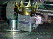
I got two 40x23x6mm ring-neodym magnets (realy strong!). The area in the ring are magnets. The rest is steel.
I got a bad frequency response. only up to 5khz
The whole coil+cone+rod+spring weight about 2.35g.
Its 0.2mm wire.
Now I try thinner wire + rubbermembran instead of a spring.
Fat
diy transducer experiments
Moderators: piaptk, tragwag, Steve E., Aussie0zborn
diy transducer experiments
You do not have the required permissions to view the files attached to this post.
-
grooveguy

- Posts: 432
- Joined: Thu Jun 22, 2006 5:49 pm
- Location: Brea, California (a few miles from Disneyland)
- Contact:
Re: diy transducer experiments
Hey, Fatrecco,
Looks like you're off to a good start. Nice job winding that coil; is there clearance for it in the gap or does it rub? I would think it needs 3-point support to keep it from being angled against one side of the magnet assembly.
What are you using for a cone? Is it hollow or solid? The weight you show isn't much, but at high frequencies even a light static load is formidable. You should be able to sweep that assembly with an oscillator and determine pretty quickly what the resonance is. Response above resonance is going to drop quickly, and you'll have to use motional feedback or lots of EQ to overcome it. Best performance is probably going to be achieved with a very stiff assembly and lots of watts.
Best of luck, keep us informed, please!
Re: diy transducer experiments
thanks,
the gap is 1.5mm. The cone is out of copy-paper which is saturated with cyanacrylat.
In my first build, I use two v-springs to avoid a rubbing coil. But I removed one of them, cause I thought it will block higher frequencies. I testet it with white noise and found no high freqs excluded of a 10khz peak. When I put single sinus signals into the transducer, I got them in the output When I play music over the transducer(with RIAA) and hear the result with a phono-amp, it sounds holow.
Try
the gap is 1.5mm. The cone is out of copy-paper which is saturated with cyanacrylat.
In my first build, I use two v-springs to avoid a rubbing coil. But I removed one of them, cause I thought it will block higher frequencies. I testet it with white noise and found no high freqs excluded of a 10khz peak. When I put single sinus signals into the transducer, I got them in the output
Try

Re: diy transducer experiments
Hey friend,
Have you tried making the bottom-most portion aluminium? This might help saturate the flux where you want it, in that gap.
Try it our on the simulator and see if it does anything!
Have you tried making the bottom-most portion aluminium? This might help saturate the flux where you want it, in that gap.
Try it our on the simulator and see if it does anything!
-
EpicenterBryan

- Posts: 738
- Joined: Sun Aug 10, 2014 9:01 pm
- Location: Eugene, OR USA
Re: diy transducer experiments
Hey Fatrecco,
You might want to ask "Fela Borbone:" about this. He did some great simulations on the Groove Scribe thread.
Bryan
You might want to ask "Fela Borbone:" about this. He did some great simulations on the Groove Scribe thread.
Bryan
-
Fela Borbone
- Posts: 272
- Joined: Thu Mar 07, 2013 5:22 pm
- Location: Valencia, Spain
Re: diy transducer experiments
Hi,
You have agood start! I like westrex like suspension too! It should feel stiffer than a speaker.maybe you want to add something else to keep coils clearing the gap when in action, other spring or silicone.
Magnetic things seem ok., maybe the gap toobi g. I prefer less turns and more current,but theres lot of trade offs.
are you using cianocrilate to bond the coil? If so be avoid breathing the vapours it prodoce when heated!!
Good luck with the project!!
..and have fun!
Re: diy transducer experiments
Thanks,
@Bahndahn: I don't understand what you mean with the aluminium in the bottom plate. The iron/steel should be nearly at the point of magnetical saturation. I think FEMM doesn't consider about saturation.
@Fela: ok I try to make it stiffer. And yes I use cyanacrylate.
fat
@Bahndahn: I don't understand what you mean with the aluminium in the bottom plate. The iron/steel should be nearly at the point of magnetical saturation. I think FEMM doesn't consider about saturation.
@Fela: ok I try to make it stiffer. And yes I use cyanacrylate.
fat

Re: diy transducer experiments
Not quite as simple as saying aluminum bobbin.... There is a trick to it to avoid eddy currents in the aluminum that will negate high frequencies. The aluminum will fight the drive coil.Bahndahn wrote:Hey friend,
Have you tried making the bottom-most portion aluminium? This might help saturate the flux where you want it, in that gap.
Try it our on the simulator and see if it does anything!
https://en.wikipedia.org/wiki/Eddy_current
Cutting, Inventing & Innovating
Groove Graphics, VMS Halfnuts, MIDI Automation, Professional Stereo Feedback Cutterheads, and Pesto 1-D Cutterhead Clones
Cutterhead Repair: Recoiling, Cleaning, Cloning of Screws, Dampers & More
http://mantra.audio
Groove Graphics, VMS Halfnuts, MIDI Automation, Professional Stereo Feedback Cutterheads, and Pesto 1-D Cutterhead Clones
Cutterhead Repair: Recoiling, Cleaning, Cloning of Screws, Dampers & More
http://mantra.audio
Re: diy transducer experiments
Copper shorting ringopcode66 wrote:
Not quite as simple as saying aluminum bobbin.... There is a trick to it to avoid eddy currents in the aluminum that will negate high frequencies. The aluminum will fight the drive coil.
https://en.wikipedia.org/wiki/Eddy_current
Re: diy transducer experiments
Even simpler
Cutting, Inventing & Innovating
Groove Graphics, VMS Halfnuts, MIDI Automation, Professional Stereo Feedback Cutterheads, and Pesto 1-D Cutterhead Clones
Cutterhead Repair: Recoiling, Cleaning, Cloning of Screws, Dampers & More
http://mantra.audio
Groove Graphics, VMS Halfnuts, MIDI Automation, Professional Stereo Feedback Cutterheads, and Pesto 1-D Cutterhead Clones
Cutterhead Repair: Recoiling, Cleaning, Cloning of Screws, Dampers & More
http://mantra.audio