Heater Supply Schematics

Anything goes! Inventors! Artists! Cutting edge solutions to old problems. But also non-commercial usage of record cutting. Cost- effective, cost-ineffective, nutso, brilliant, terribly fabulous and sometimes fabulously terrible ideas.

Moderators: piaptk, tragwag, Steve E., Aussie0zborn

Post Reply
User avatar
jesusfwrl
Posts: 365
Joined: Thu May 16, 2013 2:24 pm
Location: Earth
Contact:

Heater Supply Schematics

Post: # 37676Unread post jesusfwrl
Thu Oct 01, 2015 6:48 am

Hello Trolls,
I have recently designed a very fancy Current-Regulated Power Supply Unit for stylus heating wires, for a small company called Magnetovolt. While I cannot make this design public, I am offering here some very simple approaches to stylus heat, which we tried out and rejected as a commercial design.

They work but they all have their limitations. However, they are simple and cheap so they can definitely get you going.
heater_z.png
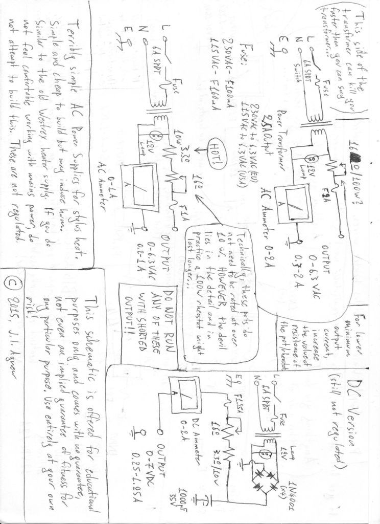
These are the simplest ones. The AC versions were even used in professional systems in the past, but are likely to induce some hum. The DC version overcomes this but none of these are properly regulated, so could drift.
heater_y.png
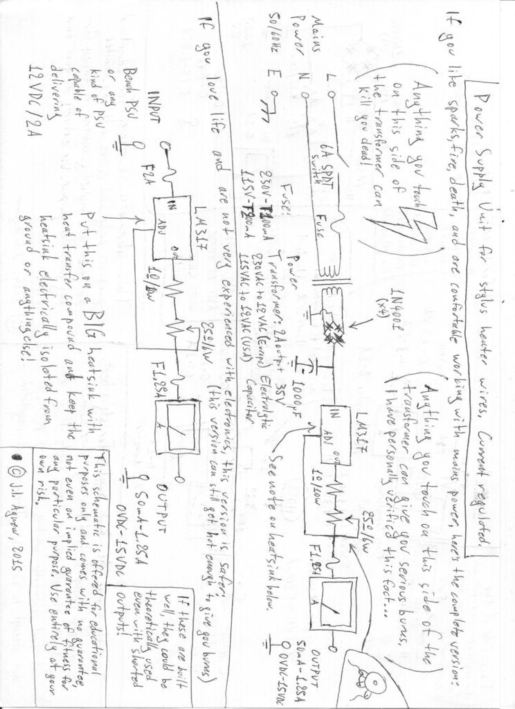
These are simple Current-Regulated versions that work well, but run pretty hot. All of these designs are a bit too simple, putting a lot of strain on the components. They will work for a bit, but can't say how long they would last. It greatly depends on the quality of the components you use.

The main thing I don't like about such designs is that plenty of current runs through the pot, which is the weakest link. You either need a very expensive industrial rheostat or you risk premature failure.

The Magnetovolt philosophy is that gear should be passed on to grandchildren and should still be as reliable as when it was made, so the final design I did was a lot more complicated, with the significant advantage that the current does not run through the pot. The whole thing runs a lot cooler. Also, it offers a very smooth and precise control of the heating current, which ranges from an almost total 0A to 1.6A, capable of accommodating all kinds of heater wire. Proper bulletproof design. It can run forever with shorted outputs and the current set to MAX!
It will come in a 2U 19" rack format, with a big Ammeter and Voltmeter on the front panel, along with a big status indicator so you always know if it's on or off. Production should start soon and I will be posting some pictures of the first units.

So, the schematics posted are good for the hobbyist on a tight budget to get started with a heated stylus setup. If you need a professional, reliable and ready-to-go solution, just wait for the Magnetovolt product. Prices should be fairly reasonable.


Image
Image
You do not have the required permissions to view the files attached to this post.
~~~ Precision Mechanical Engineering, Analog Disk Mastering ~~~
Agnew Analog Reference Instruments: http://www.agnewanalog.com

User avatar
EmAtChapterV
Posts: 244
Joined: Sun Jan 06, 2013 6:49 pm
Location: Vancouver, BC

Re: Heater Supply Schematics

Post: # 37680Unread post EmAtChapterV
Thu Oct 01, 2015 9:10 am

Mine is a former bicycle light battery charger that puts out 6.3VDC at 850 mA, run through a 5W or 10W pot with a heat sink attached and a small DC ammeter. It was dumb luck that it was just sitting around in my junk electronics pile, and has worked very well for the past sixteen years, aside from burning out an older 2 or 3 watt pot at one point.

User avatar
jesusfwrl
Posts: 365
Joined: Thu May 16, 2013 2:24 pm
Location: Earth
Contact:

Re: Heater Supply Schematics

Post: # 37690Unread post jesusfwrl
Thu Oct 01, 2015 12:16 pm

A lot of seemingly unrelated devices lend themselves to be used as heater supplies. Battery chargers are a very good starting point as they basically work on the same principle from a different perspective. Instead of adding a pot after the battery charger, you could just unsolder the current sensing resistor in the circuit and add the pot directly there. Depending on the design, it will most likely not need to be a high wattage pot. Simple battery chargers did not need a variable current so they used a fixed resistor for regulating it to a set value.
~~~ Precision Mechanical Engineering, Analog Disk Mastering ~~~
Agnew Analog Reference Instruments: http://www.agnewanalog.com

User avatar
Soulbear
Posts: 526
Joined: Tue Nov 04, 2014 11:56 am

Re: Heater Supply Schematics

Post: # 37694Unread post Soulbear
Thu Oct 01, 2015 3:40 pm

Hi There,
I came across a version of this whilst doing some research for an electro-plating supply on a side project of mine. I've modified it only slightly and I thought it might be useful to fellow Trolls as a simple to construct Stylus Heating Control Circuit which uses a minimum of inexpensive and easy to source parts.
LM317+2N3055 Stylus Heater Power Supply.jpg
The total cost of these components is around the £20/$30 mark so shouldn't break the bank.The most expensive item is the (Combined) Digital Voltmeter/Ammeter and even that only runs to around £4/$6 on the bay, the heatsink for the 2N3055 is next at around £2/$3 the rest can be sourced for pennies and cents.
I hope fellow Trolls might find this usefull :wink: :P :P :D :D Soulbear
You do not have the required permissions to view the files attached to this post.

User avatar
opcode66
Posts: 2700
Joined: Sun Nov 08, 2009 10:56 pm
Contact:

Re: Heater Supply Schematics

Post: # 37697Unread post opcode66
Thu Oct 01, 2015 7:35 pm

FYI, I've been using an unregulated version for some time now with no issues. I think part of this is in implementation. I use more than one 10W resistor to perform the initial current reduction. That offsets the heat into two ceramic casings. The overall heat on any one component seems to be much less when split out like that. Therefore, the output isn't affected by changing resistance due to heat and is very stable. I get no wiggle of the ammeter that I can detect with a stable reading over time. It is good enough for my purposes. However, regulated power supply would be the ideal situation. FYI, Neumann just put a rheostat on rectified 12V DC. Unregulated DC implementation but with no other resistor involved. Just a really expensive rheostat. The kind that would cost you $50 or so.

I think in total, after the project box, the knob cap, the componenets, the ammeter, connectors and wall wort power supply you are looking at more like $50 - $55 in total. Plus your time to drill the box and assemble. Putting meters into an interface panel is always a distinct joy. You have to plan your box just so to avoid things colliding once you are ready to close it up.

I posted a much more abbreviated version of this in my Bladerunner thread. Nice to see a fresh face contribute. This is a much more detailed explanation. Bravo!
Cutting, Inventing & Innovating
Groove Graphics, VMS Halfnuts, MIDI Automation, Professional Stereo Feedback Cutterheads, and Pesto 1-D Cutterhead Clones
Cutterhead Repair: Recoiling, Cleaning, Cloning of Screws, Dampers & More
http://mantra.audio

User avatar
Kiss the Groove
Posts: 24
Joined: Tue Jan 31, 2012 11:42 am

Re: Heater Supply Schematics

Post: # 37700Unread post Kiss the Groove
Thu Oct 01, 2015 8:28 pm

Hi Soulbear,

Are you sure that's drawn correctly? I don't see a reason for the diode being connected to the right end of the 220 ohm resistor, and as drawn, the available output current is rather limited. In fact, the higher the voltage setting, the less output current is available. It makes more sense to me if the diode is connected to the LM317 output instead:
Stylus heater reg rev.jpg
Here's an analysis for those who are interested (or who are seeking a cure for insomnia :wink: ).

The purpose of the 2N3055 emitter-follower is twofold: Firstly, it boots the available heater current above the 500 mA available from a "barefoot" LM317. Secondly, its high maximum power dissipation rating (115 W) makes it a more suitable series-pass element than the LM317.

The maximum available heater current is equal to the base drive current multiplied by the beta, or DC current gain, of the 2N3055. Beta is highly variable from device to device, and it also varies widely over temperature and collector current, but for the 2N3055 we can assume a typical value of about 100.

In the original diagram, the base drive current is equal to the source current supplied by the LM317 through the 220 ohm resistor, minus the current through the potentiometer. The LM317 maintains a constant 1.25 volts across the 220 ohm resistor, so the source current is (1.25 / 220) = 5.7 mA regardless of the voltage setting or load current.

Even disregarding the base drive current lost to the potentiometer, the maximum available heater current is (5.7 mA * beta) = 570 mA, which is half of the 1 A that's typically quoted for heater supplies. And since the 2N3055's actual beta might be as low as 50 in the operating range of interest, the output might be limited to as little as 280 mA.

Connecting the diode directly to the LM317 makes the entire LM317 output current (at least 500 mA) available to the base of the 2N3055, so the available heater current is essentially unlimited. The output also exhibits far better load regulation.

If you're wondering about that 6A4 diode, its purpose is to allow the output voltage to be adjustable down to zero volts. The 4.7k potentiometer varies the LM317's output voltage over the range of 1.25 volts (at zero ohms) to 27.95 volts (at 4.7k ohms). Without the diode, the output voltage would be equal to the LM317 output voltage minus the 2N3055's base-emitter voltage drop, which is about 0.7 V, so the output would only be adjustable down to (1.25 - 0.7) = 0.55 volts. Inserting the diode adds an additional ~ 0.6 V drop, so the output minimum becomes (1.25 - 0.6 - 0.7) = -0.05 volts (= zero volts, since it can't go negative). The 6-amp, 400 PIV diode is a bit of overkill, by the way... a 1N4001 would work fine.

A couple of other points: This circuit has no designed-in current limiting, so a fast-acting fuse should be wired in series with the input to protect the devices in case of an output short-circuit. Also, a 27 volt maximum output seems rather high for a stylus heater, and if the input supply is lower than about 30 V, some part of the potentiometer's range will be unusable. I'd suggest 2.2k ohms, which would reduce the maximum output to 12.4 volts.

Yes, there are a lot of ways to heat a stylus!
You do not have the required permissions to view the files attached to this post.

User avatar
Soulbear
Posts: 526
Joined: Tue Nov 04, 2014 11:56 am

Re: Heater Supply Schematics

Post: # 37707Unread post Soulbear
Fri Oct 02, 2015 5:52 am

Hi KTG,
Thanks for the circuit explanation and updating it, and yes, I was curious as to why the diode needed to be so beefy. I just pulled that circuit off the web for a little side project of mine. I also shoulda spotted that the 4.7K pot would wind the output too far up for most heaters. In my defence I must say I'm currently using 25V+ supplies so the 4.7K pot was OK for that application. I used to be a "Clatter and Bang" Old School Electrician though I've been "off the tools" over 30years and even when I was "on the tools" Electronics in general mystified me, I'm still not convinced that Witchcraft isn't in some way involved te he :wink: :P :D Soulbear

User avatar
Soulbear
Posts: 526
Joined: Tue Nov 04, 2014 11:56 am

Re: Heater Supply Schematics

Post: # 37713Unread post Soulbear
Fri Oct 02, 2015 12:08 pm

Hi There,
Just for any Trolls who wouldn't know a soldering iron from a pencil :-
Combination Volt & Ammeter2.jpg
Fuse Holder.JPG
PWM and Display.JPG
Wall Wart.JPG
Combined Volt/Ammeter+Inline Fuseholder+Pulse Width Modulator C/W %Duty Cycle Display+12V 1000mA Wall Wart £20/$30 + a Little Box to make it look a propper Pro-Job- Done & Done, Happy Cutting :P :P :D :D Soulbear
You do not have the required permissions to view the files attached to this post.

User avatar
Kiss the Groove
Posts: 24
Joined: Tue Jan 31, 2012 11:42 am

Re: Heater Supply Schematics

Post: # 37717Unread post Kiss the Groove
Fri Oct 02, 2015 12:38 pm

Soulbear,

I grew up building stuff with relays, so I love "clatter and bang!" ICs and MOSFETs are just too darn quiet.

But I'm also passionate about reverse-engineering things because of what I might learn that I can incorporate into my regular work as an EE. When I see something unusual in a schematic, I just have to reduce it to either (1) Hey, that's a neat idea, or (2) Nope, it's just a goof. My motto has always been "Steal only from the best." :D

Opcode66,

The plain ol' resistors make sense. If the heater is 3 ohms, then a 20-ohm series resistance is close to a constant-current source all by itself; it just dissipates 87% of the total power as waste heat, as you've noted.

That's one thing that all the heater supplies I've seen here have in common: they all use a series element, either active like the LM317T or 2N3055, or passive like Neumann's rheostat or Opcode's 10-watt resistors. Either way, they're going to get hot. An adjustable switching regulator would be more like 90% efficient, but circuit layout is critical, and it takes a lot more skill to hand-build one that doesn't oscillate or radiate.

Here's another idea to consider: Use a Variac and a step-down transformer instead:
Stylus heater variac.jpg
The efficiency of this arrangement is probably better than 95%, the voltage regulation is very good, and because of the class-2 transformer and no AC mains wiring, it's completely safe. Variacs like this one...
variac_picture.jpg
... are routinely available on ebay for less than $40 used. Even the smallest, lowest-rated ones are fine, since the stylus heater is only a few watts. Likewise, a small class-2 "wall wart" or "doorbell" transformer with a secondary of 8 to 12 volts and 16 to 24 VA would be appropriate.

Plugging the Variac into the switched outlet with the vacuum pump ensures that the heater is deenergized when suction is off (important), and the switch in the secondary circuit deenergizes the heater when the cutterhead is lifted. If desired, an AC ammeter can be inserted in the secondary circuit to provide a check during cutting that the heater has not opened.

LATE ADDITION: Soulbear, is that PWM-regulator/meter a commercial device? It looks like a winner!

Regards -- KtG
You do not have the required permissions to view the files attached to this post.

User avatar
Soulbear
Posts: 526
Joined: Tue Nov 04, 2014 11:56 am

Re: Heater Supply Schematics

Post: # 37719Unread post Soulbear
Fri Oct 02, 2015 1:34 pm

Hi KTG,
Yup, they are all over the bay for peanuts, I currently own 4 of these, I'm hopefully incorporating them into my Lathe for Leadscrew Feed Motor Contol. Gonna attempt to correlate % Duty Cycle Indication with Cutting Duration and make a Cutting Chart so I Know what Duty Cycle to dial in for any given length of recording. I've found them to be pretty-well made and they are really OK value wise. I've been experimenting driving a small gearmotor from two of these, simultaneously connected through a pair of Power Diodes (One on the output of each PWM) to prevent the higher set duty cycle PWM reverse powering the lower set PWM. One is set at a Higher duty cycle for lead-in/run-out whilst the other is at a lower duty cycle for cutting. There is no measurable feedback from the Higher Duty Cycle into the Lower Duty Cycle PWM because of the diodes, and it seems to give a super smooth transition From High-Speed Lead-In to Cutting Speed and back to High Speed for the Run-Out. Because of this configuration there is no switching pause or delay on the speed changeover. On the Clatter and Bang front, although I could probably do it with an Arduino or such-like, but I'm too old a dog to be learning how to program stuff when I've got the experience of using proven "Old-School" kit. I'm doing the Switching via a Toothed Belt Driven 50:1 Worm Gearbox driving a HoneyWell Type 8 Gang Cam-Operated Microswitch Cycle Timer and 24V 11Pin Octal Type Relays, I hope you approve te he. A Velleman PWM Kit cost me twice as much and with no display feature. Here's a link to the supplier of my last purchase http://www.ebay.co.uk/itm/Max-8A-DC-6-30V-12V-24V-Motor-PWM-Speed-Controller-With-Digital-Display-Switch-/151483541434?hash=item23451f67ba I hope I've done that right! Happy Cutting :P :P :D :D Soulbear

User avatar
jesusfwrl
Posts: 365
Joined: Thu May 16, 2013 2:24 pm
Location: Earth
Contact:

Re: Heater Supply Schematics

Post: # 37727Unread post jesusfwrl
Sat Oct 03, 2015 8:37 am

KTG, the LM317 in the TO-220 or the TO-3 package is rated at 1.5A and can dissipate 20W. More than enough to supply what is needed for stylus heat on its own.
For the commercial deign I am not using the LM317 though, but a similar device with much higher ratings. More expensive though, and not as common. Not that it really needs the higher ratings, but it is a more bulletproof device.
Efficiency was not of primary concern, but reliability and longevity were.

A PWM supply is a very common way of adjusting heating, but I expect it would perform even worse that an AC supply in terms of hum if the frequency lies within the AF range. Outside the AF range might be fine, or not. Never tried.

The particularity of stylus heating is that you're not just heating a toaster, it is a coil of wire on a stylus that sits only millimetres away from sensitive driving and feedback coils. Even a 50/60Hz sine wave is capable of inducing hum, so a pulse train would be a bit too much of a risk. It is not about the supply circuit itself, but the actual load.

DC heater supplies were invented to prevent the hum that resulted from AC supplies in disk cutting. However, AC supplies were tolerated for decades, so can't be that bad.

The variac-transformer combination is an excellent idea for a simple AC supply, with the only downside being the same as if you would use an adjustable constant voltage source such as a bench PSV: Heater wires do not always go by Ohm's law, since their resistance can vary with temperature and age.
~~~ Precision Mechanical Engineering, Analog Disk Mastering ~~~
Agnew Analog Reference Instruments: http://www.agnewanalog.com

User avatar
Kiss the Groove
Posts: 24
Joined: Tue Jan 31, 2012 11:42 am

Re: Heater Supply Schematics

Post: # 37729Unread post Kiss the Groove
Sat Oct 03, 2015 2:52 pm

Hi jesusfwrl,

You're right, the LM317T is rated 1.5 A. My most recent usage was the LM317M, so I had 500 mA on my mind.

On the issue of power dissipation, I'll accept that the LM317T can probably dissipate 20 W (although the Fairchild data sheet says only "internally limited"). My point was that the 2N3055 in the circuit offered by Soulbear is a more suitable series-pass element than the LM317. I'll support that general statement by pointing out that the Theta(J-C) for the LM317T is three times higher than for the 2N3055, and the abs-max junction temperatures are 125C vs. 200C. All of which is hair-splitting for a stylus heater supply, but my spacecraft/high-rel design experience impels me to think conservatively, even in the commercial world.

Anyway, my purpose in commenting on Soulbear's post was really to help folks understand some of the details and tradeoffs in circuit design.
You wrote:I am not using the LM317 though, but a similar device with much higher ratings.
Something with an "LT" prefix, perhaps? That would certainly explain the higher cost. :wink:

As far as 50/60 Hz AC heating, I've been wondering just how much hum it induces in the final recording. I'd consider it a real possibility if the heater wire were loosely wound, due to vibration, but maybe not if the wire is cemented to the stylus. Somebody must have peformed an empirical test of this in the last 70 years, eh?

I agree that I would not consider driving the heater from a raw PWM source of any frequency. A switchmode power supply chosen for its high efficiency would need the usual output filtering to provide a low-ripple DC output. I've ordered one of those "ebay special" PWM controllers to see just how it's designed, but I'm guessing it has little or no output filtering, instead depending on the motor winding inductance.
You wrote:Heater wires do not always go by Ohm's law, since their resistance can vary with temperature and age.
Oh, that law is always in force... It's not Mr. Ohm's fault that the resistance is highly variable and nonlinear!

I look forward to seeing your final product.

Regards -- KtG

Post Reply