-
Steve E.

- Site Admin
- Posts: 1949
- Joined: Fri Jun 24, 2005 3:24 pm
- Location: Brooklyn, New York, USA
- Contact:
Re: Presto 6N guidance suggestions? (piecing together)
Oh, that's so great!

Re: Presto 6N guidance suggestions? (piecing together)
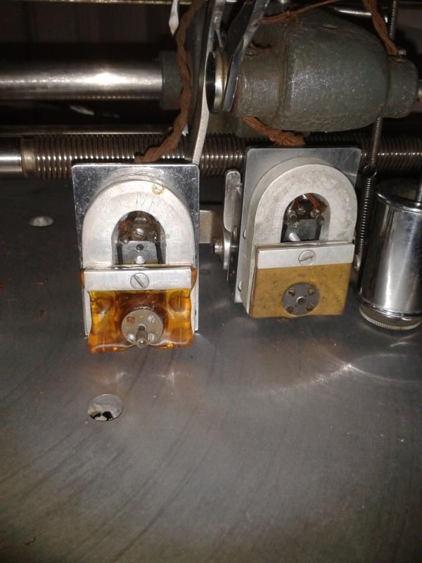
So I have two Presto 1-C cutter heads. They seem mostly the same but the dampening matterial. One is a clearish amber. And one is more of a custardy looking foam.

Both heads measure at 74 or so ohms dcr...which I suppose pegs them for 500ohm heads. I think I will leave them wound that way and just use a cutter amp with a 500ohm winding on the OT. I will think these could stand to be remagnetized.
Tim
MBL


Both heads measure at 74 or so ohms dcr...which I suppose pegs them for 500ohm heads. I think I will leave them wound that way and just use a cutter amp with a 500ohm winding on the OT. I will think these could stand to be remagnetized.
Tim
MBL

Re: Presto 6N guidance suggestions? (piecing together)
I've never seen that translucent amber rubber... All of my heads have black, except for maybe one with that opaque tan foam...
I Buy/Sell/Restore Vintage Machines/Parts and Provide Phone/In Person Tech Support
www.MichaelDixonVinylArt.com
www.LatheCutCamp.com
www.RecordLatheParts.com
www.MobileVinylRecorders.com
www.LatheCuts.com
www.MichaelDixonVinylArt.com
www.LatheCutCamp.com
www.RecordLatheParts.com
www.MobileVinylRecorders.com
www.LatheCuts.com
Re: Presto 6N guidance suggestions? (piecing together)
I am a tad confused about the construction of this thing. Mostly I'm not sure how the dampening matterial is in contact with anything mechanical. The set screw doesn't thread through the disc mounted in the dampening foam/rubber does it? It seems that it feeds straight through these discs.
Tim
MBL
Tim
MBL

Re: Presto 6N guidance suggestions? (piecing together)
Hi,
The damping material is coupled to the armature directly via the two clamping disks. The bottom disk is threaded and soldered to the armature. Then the rubber damper is placed on top of the disk and the upper clamp disk is dropped on top. 4 small brass machine screws clamp the whole assembly together. Does that make sense?
Mark

Re: Presto 6N guidance suggestions? (piecing together)
That's the "Prestoflex" referred to in the literature about their heads. It (at one time) was a very soft but firm rubbery material. Not as flexible as latex, but more like a very soft plastic.I've never seen that translucent amber rubber... All of my heads have black, except for maybe one with that opaque tan foam...
Re: Presto 6N guidance suggestions? (piecing together)
Yes it does make sense. In my case, I get the idea that the bottom disc is not threaded, but perhaps soldered to the armature....I think this based on how much of the screw goes in and where the treads catch.
Does anyone have a 500ohm head that they can measure for dcr? I want to make sure I am right about my heads.
Now the Olsen head is gonna be a mystery?!
Tim
MBL
Does anyone have a 500ohm head that they can measure for dcr? I want to make sure I am right about my heads.
Now the Olsen head is gonna be a mystery?!
Tim
MBL
Re: Presto 6N guidance suggestions? (piecing together)
Oh, and that clear rubber seems to be decently flexible...don't know that I should change it out or not.
Re: Presto 6N guidance suggestions? (piecing together)


Need to figure out some dimentions to make a console like these. It seems like it might be two separate pieces...anyone know?
Tim
MBL

Re: Presto 6N guidance suggestions? (piecing together)
I sold a 6N in a base like that, should have taken measurements first 
making lathe cuts on a Presto 6N, HIFI stereo cuts on vinylrecorder
at Audio Geography Studios, Providence, RI USA
http://www.audiogeography.com
at Audio Geography Studios, Providence, RI USA
http://www.audiogeography.com

Re: Presto 6N guidance suggestions? (piecing together)
Hey gang - I'm trying to align a new Bodine motor and home-made motor mount into my 6N but can't get the right pressure onto the idler wheels. Can someone please measure the distance between the centre of the shift-lever shoulder screw and the centre of the motor shaft for me?
many thanks!
Owen
many thanks!
Owen
Re: Presto 6N guidance suggestions? (piecing together)
the 8n is the same yes?..i can measure mine or does it have to be stock 6n..i love the double doors and hidden compartment..
biglove all and merry xmas
biglove all and merry xmas
Re: Presto 6N guidance suggestions? (piecing together)
Hi Mike - thanks for responding.
If the internal dimensions of the 8N are the same as the 6N (can't find an details/differences about the 8N at all) that'd be brilliant. Here's an internal pic of the 6N and the two points I need a measurement between (also, if the motor IS NOT centered between the mounting screws please let me know)
Thanks!

Re: Presto 6N guidance suggestions? (piecing together)
The original motor mount is off centered left to right in the picture you use above. I pulled my 6D apart when I first bought it and when I put it back together I couldn't get the correct pressure either so I turned the mount around 180 degrees and then it worked. I think it's a subtle difference. I think JCCC did the same thing when he replaced his Bodine motor and figured it out pretty quickly, his post is what lead me to realize I had mine reversed as well. I can measure mine also, but I'm on vacation away from my lathe until the 27th.
Re: Presto 6N guidance suggestions? (piecing together)
Rsimms - yes please when you're able! Many thanks
Re: Presto 6N guidance suggestions? (piecing together)
hi
6cm.. and on my 1933 stand alone MS16b,its the same.. motor appears to be in the middle.
i tried to find presto history page ,but cannot find it anymore but i found a photo of the stand alone..
http://reel2reeltexas.com/vinAd37.html
sorry for link ive gotta get my photobucket password ..its been a long time..
and ive just searched for a photo of the 8n ..nothing...
my 8n came with a grampian feedback head and the 16B has a 1D 500ohm
ill post photos soon once santa has been and gone ,also measurments of the console...
biglove
Re: Presto 6N guidance suggestions? (piecing together)
Much appreciated megamike. rsimms - if you can also send your info in when you've got a chance that'd be absolutely brilliant.
Happy new year to all
Happy new year to all
Re: Presto 6N guidance suggestions? (piecing together)
I'll do measurements tonight. Do you want both measurements, the farthest distance and the closest available? There is the pivot to adjust the pressure/speed so I want to make sure you get the most useful and accurate measurements. Which piece are you fabricating again? The upper hanger/pivot bar or the motor mount itself that holds the motor?
Re: Presto 6N guidance suggestions? (piecing together)
I'm fabricating the motor mount itself - if you could measure the distance between the centre of the shift-lever shoulder screw and the centre of the motor shaft for me, and also between each motor mount mounting screw to the centre of the motor shaft )in case it's not dead centre) that'd be awesome. Thanks for doing this for me
Re: Presto 6N guidance suggestions? (piecing together)
Pics and measurements. If you need more, let me know.
Picture 1 - Measurement from the hanger edge to the center of the bolt that holds the idlers/speed change with hanger loosened and pushed out as far as it would go toward the center is 3.325". From the edge of the 33rpm section of the capstan to the center of the same bolt is 2.150".
Picture 2 (note that the hanging columns are not centered, top of the picture faces toward the idler wheels) - Center to center from one hanger bolt hole to the other is 5.875". The motor isn't exactly centered either. In the picture, from the inside of the hanger ring to the edge of the motor protrusion is .872" and the opposite side is .853".
I marked each of these in red in the pictures. If the pics don't show up, let me know and I can host them elsewhere.